
Owner's manual
Important: Always read and follow the information box instructions. • 11
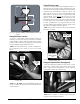
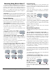
Direct Select™ Weight Placement Location
Before spinning the wheel, use direct select to indi-
cate weight placement locations as follows:
Note: When the machine is turned ON, the balancer
defaults to a 2-plane dynamic mode using standard
clip-on wheel weight locations (Clip 1 and Clip 2) and
wheel dimensions.
Clip 1 Top Center - select this location to place a stan-
dard clip weight on the inboard rim flange.
T-1 Tape Top Center - select this location to place an
adhesive weight on the inboard side of the wheel that
is the horizontal plane at the outer edge.
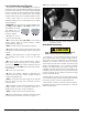
Patch Static - select this location for a patch weight
centered inside the tire. See Patch Weight Balance on
page 13 for further details.
T-2 Tape Laser Locator - select this location to place
an adhesive (hidden) weight on the outboard side of
the wheel that is a horizontal plane in the inner area.
See Laser Guided Operation™ System on page 6 for fur-
ther details.
T-3 Tape Top Center - select this location to place an
adhesive weight on the outboard side of the wheel
that is the horizontal plane at the outer edge.
Clip 2 Top Center - select this location to place a stan-
dard clip weight on the outboard rim flange.
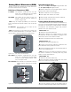
Balance Options
The indicator will illuminate to show the active bal-
ance option. Functions are as follows:
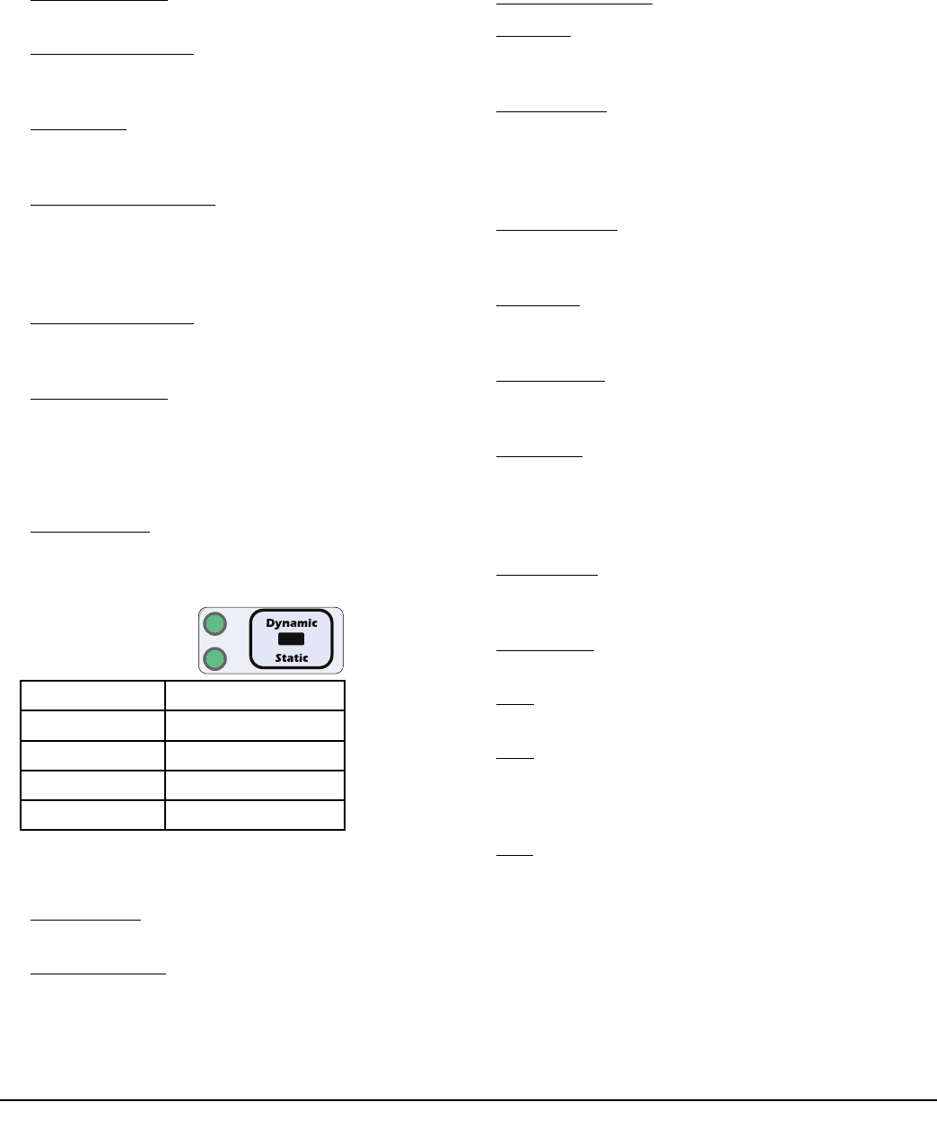
Dynamic/Static - press the respective key to cycle
through either a Dynamic, a Dynamic with Total Static
displayed, a Static, or the EB (if feature is available and
enabled, see page 12) balance mode.
* If equipped, the EB LED status light will illuminate
when mode is activated.
Behind Spoke - toggle the Behind Spoke option on or
off. See Behind Spoke on page 12 for further details.
Spoke 1/Spoke 2 - toggle to set the Spoke 1 location
and the Spoke 2 location for adhesive weights (hidden
weights).
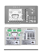
Information Box
Displays A, W, and D values, functions, and instruc-
tions for the operator. Error messages will also be
shown in this display.
Keypad Group
The operator enters wheel data information, selects
functions, and sets options using these keys.
“ Numbered” Keys - use to enter wheel data values.
Cal Mach - press and hold the SHIFT key and press 1
to activate Calibrate Machine mode. See Machine
Calibration on page 17 for further details.
RV-Lite Truck - press and hold the SHIFT key and
press 4 to toggle between either the 0.25-ounce stan-
dard roundoff (most wheels) or 0.50-ounce RV-Lite
Truck (heavy wheels) mode. The default is standard
roundoff.
Match Balance - press and hold the SHIFT key and
press 5 to select the Match Balance mode. See Match
Balance (Optimization) on page 16 for further details.
Round Off - press and hold the SHIFT key and press
6 to toggle between either 0.25-ounce or 0.01-ounce
weight increments. The default is 0.25-ounce.
Operator A/B - press and hold the SHIFT key and
press 7 to toggle between two operator memories (A
or B). The default memory is Operator A.
Hood Start - when on, sets the balancer to automati-
cally start the spin cycle as soon as the hood is low-
ered completely and the hood safety interlock system
is engaged. Press and hold the SHIFT key and press 8
to toggle Hood Start on or off. The default is on.
Ounce/Gram - press and hold the SHIFT key and
press 9 to toggle between either ounce or gram
weight measurements. The default is ounce.
Stop & Exit - press STOP to end a measurement
cycle, exit a function or a mode.
Start - press START to begin a measurement cycle, if
the hood is lowered.
Next - function key used when accessing balancer
instructions and, if balancer is equipped with an
inverter, automatically rotates tire to its next weight
placement position.
Shift - function key used when accessing balancer
modes or options.
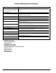
LED Indicators for
1250 Non-video
LED Status Balance Mode
Both LEDs Lit Dynamic
Top LED Lit Dynamic/Total Static
Bottom LED Lit Static
Neither LED Lit EB*