® 1175 Wheel Balancer See Balancing Your First Tire on page 1. Installation Operating Safety Maintenance Instructions Instructions Instructions Instructions READ these instructions before placing unit in service KEEP these and other materials delivered with the unit in a binder near the machine for ease of reference by supervisors and operators. 1601 J. P. Hennessy Drive, LaVergne, TN USA 37086-3565 615/641-7533 800/688-6359 www.ammcoats.com HENNESSY INDUSTRIES INC.
ii • Important: Always read and follow the instructions.
Table of Contents Important Safety Instructions . . . . . . . . .iv - vi Owner’s Responsibility . . . . . . . . . . . . . . . . . . . . . .v Operator Protective Equipment . . . . . . . . . . . . . . . .v Definitions of Hazard Levels . . . . . . . . . . . . . . . . . .v Safety Notices and Decals . . . . . . . . . . . . . . . . . . .vi Standard Safety Devices . . . . . . . . . . . . . . . . . . . . .vi Balancing Your First Tire . . . . . . . . . . . . . . . .1 Principle Operating Parts . . . . . . . . . . .
IMPORTANT SAFETY INSTRUCTIONS READ ALL INSTRUCTIONS 1. Eye and face protection recommendations: “Protective eye and face equipment is required to be used where there is a reasonable probability of injury that can be prevented by the use of such equipment.” O.S.H.A. 1910.133(a) Protective goggles, safety glasses, or a face shield must be provided by the owner and worn by the operator of the equipment. Care should be taken to see that all eye and face safety precautions are followed by the operator.
Owner’s Responsibility Definitions of Hazard Levels To maintain machine and user safety, the responsibility of the owner is to read and follow these instructions: Identify the hazard levels used in this manual with the following definitions and signal words: • Follow all installation instructions. • Make sure installation conforms to all applicable Local, State, and Federal Codes, Rules, and Regulations; such as State and Federal OSHA Regulations and Electrical Codes.
Safety Notices and Decals WARNING Failure to follow danger, warning, and caution instructions may lead to serious personal injury or death to operator or bystander or damage to property. Do not operate this machine until you read and understand all the dangers, warnings and cautions in this manual. For additional copies of either, or further information, contact: Hennessy Industries, Inc. 1601 J.P. Hennessy Drive LaVergne, TN 37086-3565 (615) 641-7533 or (800) 688-6359 www.ammcoats.
Balancing Your First Tire 1. Turn the machine OFF then ON (resets machine). Note: The machine wakes up using standard clip-on wheel weight locations (c1 & c2) and wheel dimensions. 2. Mount a tire/wheel on the balancer that will use standard clip-on wheel weights. Use the most appropriate mounting method. 3. Always remove any weights already attached to the wheel. 4. Enter A & D wheel dimensions using offset arm.
Principle Operating Parts Know Your Unit Compare this illustration with the unit before placing it into service. Maximum performance and safety will be obtained only when all persons using the unit are fully trained in its parts and operation. Each user should learn the function and location, of all controls. Prevent accidents and injuries by ensuring the unit is properly installed, operated and maintained.
Operating the Balancer Wheel Mounting Select the most appropriate mounting method for the wheel you are balancing. Using the proper method ensures secure mounting and safe balancer operation, and prevents damage to the wheel. On most wheels, the inner side of the wheel hub usually has the most uniform surface for wheel balancing. Always center the wheel by the most uniform shaped side of the hub to achieve the most accurate balance. 4. Thread the hub nut onto the shaft, and tighten it against the wheel.
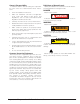
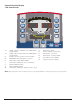
Control Panel And Display 1175 Control Panel 16 6 18 2 1 7 10 8 11 15 9 12 4 3 5E 5I 13 1-2 3-4 5I 5E 6 7 8 9 10 Digital readouts, AMOUNT OF UNBALANCE, inside/outside Digital readouts, POSITION OF UNBALANCE, inside/outside INSIDE correction position selection button EXTERNAL SIDE and STATIC correction Push button, FUNCTIONS MENU Push button, MENU selection confirmation Maximize/MENU button Minimize/MENU button Push button, unbalance reading < 0.
Operation Functions Menu See optimization unbalance section diameter inch/mm CONFIRM inch/mm width CONFIRM hood start CONFIRM approx. 0.1 -.25oz or 1-5gr on/off beep CONFIRM CONFIRM See SELF-DIAGNOSTICS section See SELF-CALIBRATION section display saver operating time in minutes CONFIRM Calibration of automatic RIM DISTANCE gauge (see SETUP) Calibration of automatic DIAMETER gauge (see SETUP) RETURN TO MEASUREMENT SCREEN Important: Always read and follow the instructions.
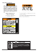
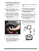
Entering Wheel Dimensions Counterweights c1-c2/STATIC/t1-t3/c1-t3 Pos A Pull out the gauge as far as the inner edge of the rim. Hold it in this position until a “beep” is heard. Pos B For clip-on weights, use gauge in the top position A. For adhesive weights, use the gauge as preferred in top position A or bottom position B. Note: Always use the round part of the striker plate resting on the rim. Indication of dimensions acquired Return the gauge to rest position.
Exact Positioning of the Adhesive Weight by Means of the Gauge with Clips - press Result of Measurement After performing a balancing spin, the amounts of unbalance are shown on the digital readouts. The illuminated LEDs 3 and 4 indicate the correct angular position of the wheel to mount the counterweights (12 o’clock). Correction of inner side - Fit the correction weight in the specific gauge seat with the adhesive part facing upwards.
Behind Spoke (Hidden Weight) The SPLIT function is used to position the adhesive weights behind the wheel spokes so that they are not visible. This function should be used only in the case of static unbalance or where the hidden adhesive weight is to be applied on the outside. Input the wheel dimensions and do a spin. 15 30 - Correction position 1 (indicator 1) Start the SPLIT function as follows: 30 15 - Place the wheel in the outside unbalance correction position.
Match Mount - This function serves to reduce the amount of weight to be added in order to balance the wheel - It is suitable for static unbalance exceeding 1.5oz (30g). TIRE IN POSITION INDICATION - Mark the rim (12 o’clock position). Turn the tire on the rim until the marks correspond to obtain the optimization shown on the display. No previous unbalance measurement Unbalance already measured CANCEL OPTIMIZATION IN ANY PHASE. Unbalance measured - It improves the residual eccentricity of the tire.
Correction Modes To check the type of correction selected, hold the but- From the measurement screen, press or button to select the type required. If a spin has already been performed, the processor automatically recalculates, for each change of mode, the amounts of unbalance according to the new calculation. ton , while on the matrix display the rim symbol appears with the correction weights flashing in the right application position.
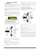
Manual Dimension Presetting (Use only in particular cases or for test) c1-c2/STATIC/t1-t3/c1-t3 Wheel Rims (use for setting dimensions in AUTO CALIBRATION) - Preset using distance “A” for the inside of the wheel from the machine. Note: This setting is also valid for the correction modes STATIC/t1-t3/c1-t3. t1-t2 Rims W dt1 dt2 A At1 At2 D To go to these functions: - Setting: Press - Setting: or - press one of the two buttons for more than 2 seconds.
c1-t2 Rims dc1 dt2 Ac1 At2 - Setting: To go to these functions: - press one of the two buttons for more than 2 seconds. - to change press one of two buttons. - to change press one of two buttons. - to change press one of two buttons. Note: when dt2 is not set, dt2 = dc1 + 2” is automatic. 12 • Important: Always read and follow the instructions.
Self-Calibration For machine self-calibration proceed as follows: - Fit a wheel with steel rim of average dimensions on the shaft. Example 6" x 14" (± 1") - Preset the exact dimensions of the wheel mounted. Display Saver A display saver function can be enabled which allows temporarily replacing the information on the display with moving symbols.
Maintenance Instructions Diagnostic Procedures The balancer requires only minor maintenance to keep the unit operating properly. 1. Keep the display clean and clear. Use a damp cloth. Do not use cleaners or solvents which leave oily or filmy residues behind. After Balance Vibration Problems If vibration is still present after balancing the wheels and driving the vehicle on smooth pavement, remove the wheels and recheck the balance. If a wheel is out of balance the cause maybe: 2.
Installation Instructions Features A factory trained COATS® Service Technician must perform the install, setup, and initial test procedures on your wheel balancer. Do not attempt to install and setup the unit yourself. Accurate and reliable operation of your unit depends on proper installation. Please contact COATS® directly at 1-800-688-9240 for the Certified Service Partner nearest you.
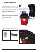
Floor and Space Requirements Unpacking the Unit The balancer must be located on a flat floor of solid construction, preferably concrete. The balancer must sit solidly on its three feet. If the balancer is not level, does not sit solidly on its three feet, or is placed on an unstable floor, the balancer will not function properly and may produce inaccurate balance readings. Do not operate the balancer while it is on the pallet.
Hood Installation 1. Install plastic bushing on end of hood tube. 2. Insert hood tube through hole and slide through hood mounting bracket. The bushing will only fit one way due to its molding. 3. Install second plastic bushing on the end of the hood tube protruding from the bracket. 4. Slide on the stop ring. The set screws may need to be loosened to install slide ring. Adjust the stop ring so the notch is parallel to the floor when the hood is in the down position. 5.
85008884 01 06/08 © Copyright 2007 Hennessy Industries and COATS All Rights Reserved Printed in USA