Models 1100, 1150-2D Wheel Balancers See ÌBalancing Your First Tire on page 4. Model 1150-2D Shown Safety Set-up Operation Maintenance Instructions Instructions Instructions Instructions READ these instructions before placing unit in service. KEEP these and other materials delivered with the unit in a binder near the machine for ease of reference by supervisors and operators. 1601 J. P. Hennessy Drive, LaVergne, TN USA 37086 615/641-7533 800/688/6359 www.ammcoats.com HENNESSY INDUSTRIES INC.
IMPORTANT SAFETY INSTRUCTIONS READ ALL INSTRUCTIONS 1. Eye and face protection recommendations: “Protective eye and face equipment is required to be used where there is a reasonable probability of injury that can be prevented by the use of such equipment.” O.S.H.A. 1910.133(a) Protective goggles, safety glasses, or a face shield must be provided by the owner and worn by the operator of the equipment. Care should be taken to see that all eye and face safety precautions are followed by the operator.
Owner’s Responsibility To maintain machine and user safety, the responsibility of the owner is to read and follow these instructions: • Follow all installation instructions. • Make sure installation conforms to all applicable Local, State, and Federal Codes, Rules, and Regulations; such as State and Federal OSHA Regulations and Electrical Codes. • Carefully check the unit for correct initial function. • Read and follow the safety instructions. Keep them readily available for machine operators.
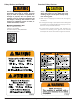
Safety Notices and Decals Standard Safety Devices CAUTION Failure to follow danger, warning, and caution instructions may lead to serious personal injury or death to operator or bystander or damage to property. Do not operate this machine until you read and understand all the dangers, warnings and cautions in this manual. For additional copies of either, or further information, contact: Hennessy Industries, Inc. 1601 JP Hennessy Drive LaVergne, TN 37086 (615) 641-7533 or (800) 688-6359 www.ammcoats.
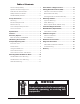
Table of Contents Owner’s Responsibility............................................ iii Direct Select™ Weight Location ........................... 12 Operator Protective Equipment .............................. iii Setting Wheel Dimensions (DIM) .......................... 12 Definitions of Hazard Levels ................................... iii Definition of Dimensions (DIM) ............................ 12 Safety Notices and Decals ......................................iv Basic Wheel Data Entry ......
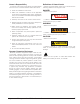
Set Up Instructions Machine Set Up Receiving The shipment should be thoroughly inspected as soon as it is received. The signed bill of lading is acknowledgement, for the carrier, of receipt in good condition of the shipment covered by our invoice. If any of the goods called for on this bill of lading are shorted or damaged, do not accept them until the carrier makes a notation of the shorted or damaged goods on the freight bill. Do this for your own protection.
Specifications Features Wheel Diameter Range 8 - 30 inches (203 - 762 mm) • Automatic Data Entry for Offset and Diameter - Manual Entry Backup on all Parameters (1150-2D only) Wheel Width Range 2 - 20 inches (51 - 508 mm) • Static-on-Screen™ • Direct Select™ Weight Placement Location Maximum Outside Tire Diameter Up to 44 inches (1016 mm) Maximum Tire/Wheel Weight 150 pounds (68 Kg) Mounting Shaft Diameter 40 mm Resolution (Round Off Mode) 0.25 ounce, position 1.
★Balancing Your First Tire 1. Turn the machine OFF then ON (resets machine). 7. Note: Wait for wheel to stop before raising the wheel guard. The machine wakes up using standard clip-on wheel weight locations (Clip 1 & Clip 2) and wheel dimensions. 2. Raise hood after tire stops rotating. 8. Mount a tire/wheel onto balancer that will use standard clip-on wheel weights. Use the most appropriate mounting method. Rotate wheel until Inboard weight position bar blinks.
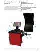
Principle Operating Parts Know Your Unit Compare this illustration with the unit before placing it into service. Maximum performance and safety will be obtained only when all persons using the unit are fully trained in its parts and operation. Each user should learn the function and location, of all controls. Prevent accidents and injuries by ensuring the unit is properly installed, operated and maintained.
Note: Throughout this manual, wheel weights are referred to as Clip-on or Tape-A-Weight®. Figure 4 shows an example of each weight. Clip-on Weight Using The Offset Arm When not in use or when prompted by the balancer instructions, store the offset arm in the home position as shown in figure 6. Tape-A-Weight® Figure 4 - Corrective Weight Examples. For Best Results, use BADA® Brand Wheel Weights. Power Switch The ON/OFF switch location (figure 5) is at the back of the balancer; below the weight tray.
Be sure to place the offset arm on the wheel flange at the clip-on weight location as shown, figure 8. Important: The A2 measurement must be at least 2 inches greater than the A1 measurement. A1 At least 2-inch minimum difference A2 Figure 8 - Clip-on Weight Location Viewed on a Cut-Away Rim for Clarification Note: Use the offset arm to automatically measure the A & D dimension for all balancing modes.
Control Panel Layout 1 5 2 6 2 4 3 7 Figure 12 - Control Panel Feature Reference (Model 1150 Shown) Control Panel Function and Review 1 Weight Display Windows Two weight display windows, one Inboard and one Outboard, are positioned above the Wheel Cross-section Diagram. After a wheel measurement cycle, the balancer calculates the corrective weight amount and indicates it in the appropriate display window. All weight readings are shown in Ounces or Grams.
Key Group 5 If you press/select ... Then indicator illuminates/displays... Match that Match Balance (Optimization) mode is activated. Spoke (1150-2D only) that Behind Spoke mode is activated Toggle to activate / select location 1 or location 2 for adhesive weights. Calibration that Machine Calibration mode is activated. Function+Calibration that Arm Calibration mode is activated. Dynamic or Static the Balance mode that is activated.
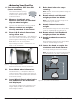
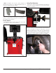
Mounting Wheel On Balancer Shaft Standard Back Cone Mounting Most original equipment and steel wheels can be mounted properly using this method. The wheel is centered on a cone from the inner side of the hub. CAUTION Avoid back injury, seek assistance when lifting heavy tire/rim assemblies onto the balancer shaft. CAUTION Faceplate Failure to tighten the hub nut properly may result in the wheel dismounting, causing personal injury and property damage.
Standard Front Cone Mounting A wheel should be centered by the outer side of the hub only when the inner surface will not provide an accurate surface to center on. Faceplate Shaft Alternate Mounting If the wheel has a protruding outer hub which will not permit the use of the pressure cup, or the cup will not permit the hub nut to engage at least four turns of the shaft, this alternate method should be used.
Direct Select™ Weight Location Setting Wheel Dimensions (DIM) Before spinning the wheel, use direct select to indicate weight placement locations on the wheel as follows: Before a wheel can be balanced, wheel dimensions must be entered into the computer. Definition of Dimensions (DIM) A = Offset The distance measured from the balancer (“0” on offset arm) to inner plane of the rim (inner weight location).
Basic Wheel Data Entry 1. Direct Select™ an Inboard weight location (Clip 1, or T1 Tape) and an Outboard weight location (T2 Tape, T3 Tape or Clip 2). 2. Position offset arm at clip weight location; wait for BEEP (A & D enters automatically). If the T2 Tape location is selected, then move the offset arm from the clip weight location to the inner area of the wheel; up against the rim at the outboard weight placement location; wait for BEEP (A2 & D2 enters automatically).
Balancing A Wheel Static Balancing A variety of wheel configurations can be balanced using this wheel balancer. Read through this section, it will help in determining which balancing mode and options are best suited for certain wheel assemblies. Choose a static balance to balance a wheel using one plane for correction. Place the single corrective weight at top-dead-center (12 o’clock) on either flange, at the center of the rim channel, placed inward either side, or split on either sides.
Corrective Weight Placement Behind Spoke Mode (1150-2D only) “Splitting” the T2 Tape corrective weight amount is used to hide the adhesive weight behind two rim spokes. 1. When the unbalance is displayed, rotate wheel until Inboard center bar blinks. Attach Inboard corrective weight at top-dead-center. 2. Next, rotate wheel until the outboard center bar blinks. 3. Select the Behind Spoke mode option. “SP1” will display in the static display window. 4.
Match Balance (Optimization) Match Balance Mode If you choose to use Match Balance to correct for a condition, such as a large static unbalance, then follow the machine prompts and instructions for the MATCH BALANCE procedure as outlined in the following steps. Match Balance involves the loosening of tire beads and the inflation of a tire.
Calibration Program Important: Be sure to use the correct calibration weight amount: a 4-ounce calibration weight with the ounce option or a 100-gram calibration weight with the gram option activated. Be sure to deactivate the Round Off option. Important: It is critical that the inner weight be placed accurately to achieve proper calibration.
Arm Calibration 8. Return arm to home position. Important: Always perform the Arm Calibration immediately after Machine Calibration. The balancer software will not permit it otherwise. During Machine Calibration, the balancer software calculates both the A (offset) and W (width) dimensions. The Arm Calibration gives the balancer software a reference point to the edge of the faceplate and home position.
Maintenance Instructions Use common sense, this is an electrical device. Exposing the balancer to water, either by hose or bucket, or by exposure to rain or snow, may cause risk of shock or electrocution to operator or bystanders. Place, store, and operate the balancer only in a dry, sheltered location. CAUTION Do not hose down with water or bucket wash the balancer. Extensive damage to the balancer will result.
Diagnostic Procedures Troubleshooting After Balance Vibration Problems If vibration is still present after balancing the wheels and driving the vehicle on smooth pavement, remove the wheels and recheck the balance. If a wheel is out of balance the cause maybe: • Wheel was not mounted/centered correctly on the balancer. • A weight has come off the wheel (possibly the wrong clip style). Remove the other weights from the wheel and rebalance. • Foreign material inside the tire.
Error Description 100, N01, CAL Exceeded 5 degree range between placement of calibration weight from outside flange to inside flange. 100, N02, CAL Calibration wheel is more than 1-ounce out of balance. Calibration is rejected. 100, N03, CAL Calibration wheel is more than 0.25-ounce but less than 1-ounce out of balance. Calibration is stored, but with warning. Overload Protection - The balancer’s motor is overload protected per UL requirements.
Glossary ALUS -Alloy wheel mode that typically requires the use of one or two adhesive weights for correction. Balancer Flange – Disk that mates with the disk of the wheel mounted to the balancer. The flange also serves to keep the wheel perfectly perpendicular to its axis of rotation. Spin – Procedure starting from the action that causes the wheel to rotate and the successive free rotation of the wheel. Quick Nut – Device for clamping the wheel to the balancer.
Important: Always read and follow instructions.
85609415 01 5/2014 © Copyright 2014 Hennessy Industries and COATS®.