
Specifications
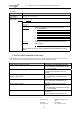


AT command set for XX Siemens mobile phones and modems
_________________________________________________________________________________________
_________________________________________________________________________________________
Document No.: A30880-A10-A001-XX-
D376
Revision: Master R75
Revision Date: 29. September, 2004
126
Table 3-3: Using escape characters in GSM commands
Note:
When reading phonebook records, there is NO replacement. Every character will appear in normal GSM
character set notation (like the left column in the example above).
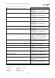
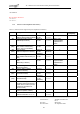
3.2 S Registers
This section provides the meanings of S registers used in the modem:
S Register Function (default values in bold type)
S 0 The number of rings before the call is answered
default: 0 (i. e. does not answer)
S 3
Command termination character and first character of response trailer (CR)
S 4
Second character of response trailer (LF)
S 5
Editing character; erases the previous character (BS)
S 6 Escape character
S 7 Wait for carrier after dialing (in seconds).
default: 60
S 8 + S 9 No action
S 10 Delay between Lost Carrier and Hang up in 0.1 sec. (Default 2 = 200ms)
S 11 .. S17 No action
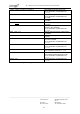
S 18 Bit 0
0
No GSM exit cause
1
With GSM exit cause
Bit 1
0
No SMS indication “+C”
1
With incoming SMS indication “+C”
S 19 ... S99 No action
Table 3-4: S-Registers
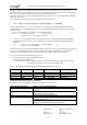
Only the following S registers can be modified by means of the corresponding ATSn=x command (where n
denotes the number of the register): S0, S3, S5, S6, S7, S8, S10; S18.
All the other S registers are used internally and thus read-only.
The contents of a single S register can be displayed via the ATSn? command (where n denotes the number of
the register). It is not possible to have the contents of multiple registers displayed at the same time.
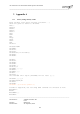
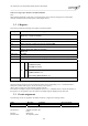
3.3 Circuit assignments
The following circuits are assigned at the mobile connector to support the exchange of data:
Name: Direction Function ITU V24 Circuit
SG Signal Ground 102