
User Manual


P/N: 192047082 (REV AA) 627NH January 2018
9
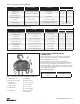
INSTALLATION
UNPACKING INFORMATION
When received, the hoist should be carefully inspected
for damage which may have occurred during shipment or
handling. Check the hoist frame for dents or cracks, the
external cords for damaged or cut insulation, the control
station for cut or damaged enclosure, and inspect the load
chain for nicks and gouges. If shipping damage has occurred,
refer to the packing list envelope on the carton for claim
procedure.
Before installing the hoist, make sure that the power supply
to which it will be connected is the same as that shown on
the nameplate located on the side of the hoist.
NOTE: See Electrical Installation instructions
INSTALLING THE SUSPENSION
A. Single Reeved Units:
For Models A, AA, B, C & F:
Remove the hook suspension and (2) suspension screws
from the packaging. Place the suspension assembly into the
recess on top of the hoist so that the adaptor body follows
the contour of the hoist. Insert the suspension screws
through the holes in the adapter and hand thread these into
the self-locking nuts enclosed in the hoist.
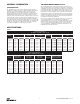
Securely tighten the screws to the recommended seating
torque (see Table 2) using a 12 point socket: 3/8" for Models
A, AA, B, C & F.
Use of impact tools (electric or pneumatic) may cause premature failure
of attaching hardware.
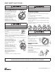
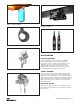
B. Double Reeved Units:
Remove the hook suspension,(2) suspension screws, (1) dead
end pin, (1) washer, and (1) cotter pin from the packaging.
It should be noted that the suspension includes a dead end
bolt and block for supporting the dead end of the load chain
as shown in Figure 7.
Place the suspension assembly into the recess on top of the
hoist. The dead end block should project through the bottom
of the hoist with the pin hole and slot aligned to the underside
of the hoist as shown in Figure 7. If these are not aligned as
shown, lift the head of the bolt from the hex recess in the
adapter and turn the bolt and block assembly and reseat
the bolt head to obtain the proper alignment. Do not change
the position of the dead end block on the bolt to attain this
alignment.
Check the position of the pin hole in the dead end block to
make sure it has not been disturbed from its factory setting.
The distance from the top of the pin hole to the bottom of
the hoist should not exceed 1/4" (6.35mm) for Models E & H.
If the distance is not correct, adjust the position of the dead
end block to obtain the proper distance (see g. 13, p 38.)
Now, insert the suspension screws through the holes in the
adapter and hand thread these into the self-locking nuts
enclosed in the hoist frame. Securely tighten the screws to
the recommended seating torque (see Table 2) using a 12
point socket: 3/8" for Models E & H.
Using other than CM supplied high strength suspension screws to
attach the suspension adapter to the hoist may cause the screws to
break and allow the hoist and load to fall.
TO AVOID INJURY:
Use only the CM supplied suspension screws to attach the
suspension to the hoist and hand torque these screws to the
recommended seating torque as specied in tables 2a and 2b. DO
NOT apply any type of lubricant to the threads of these screws.
Lubricating the threads will reduce the effort to seat the screws
and as a result, tightening the screws to the above recommended
torque may break the screw,damage the suspension adapter, strip
the nuts and/or damage the hoist frame.
SUSPENSION BOLT SHOULD BE REPLACED ANY TIME
THE SUSPENSION IS REMOVED FROM THE HOIST
ATTACHING LOAD CHAIN
Single Reeved
1. Suspend the hoist from an adequate support.
2. If replacing existing chain, remove chain block kit
from loose end of chain by removing the two (2)
screws from opposing sides of the block. Remove
lower hook assembly by removing the pin holding
the chain into the assembly.
3. Limit switch settings will need to disabled when removing
or installing chain. Refer to the limit switch section.
4. Using the connecting link, attach new chain to end
of starter chain (existing chain if replacing) and feed
through chain guides and over liftwheel. Feed enough
chain through to be able to attach the chain block kit
to the loose end of the chain by assembling the
screws and nuts into the appropriate slots and
tightening securely.
5. Attach the lower hook assembly to the appropriate end
of the chain, by inserting the end link of the chain into
the block, and securing the link with the pin.
6. Set upper and lower travel limits, before putting unit
into service. Refer to the limit switch section.
Double Reeved
1. Suspend the hoist from an adequate support.
2. Insert the last link of the load chain into the dead end
block (1) and secure it with the dead end pin, washer
and cotter pin furnished with the suspension. Ensure there
are no twists in the chain.
Do not remove the plastic ties from the load chain at this
time. After the suspension is installed, hoists with a hook
suspension can be suspended from its permanent support
and then connected to the power supply system (refer to
page 14). For hoists with a lug suspension that are to be sus-
pended from a Series 635 Low Headroom Trolley, attach the
hoist to the trolley per the following instructions.