
User Manual

P/N: 192047082 (REV AA) 627NH January 2018
40
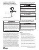
CUTTING CHAIN
CM
®
Load chain is hardened and it is difcult to cut. The
following methods are recommended when cutting a length
of new chain from stock or cutting off worn chain.
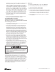
1. Use a grinder and nick the link on both sides (Figure 14),
then secure the link in a vise and break off with a hammer.
2. Use a 177.8 mm (7 inches) minimum diameter by 3.175
mm (1/8 inch) thick abrasive wheel (or type recommended
by wheel supplier) that will clear adjacent links.
3. Use a bolt cutter (Figure 15) similar to the H.K. Porter No.
0590MTC with special cutter jaws for cutting hardened
chain (25.4mm-1 inch) long cutting edge.
Figure 14. Cutting Chain by Nicking
Figure 15. Cutting Chain with a Bolt Cutter
Cutting Chain Can Produce Flying Particles.
TO AVOID INJURY:
• Wear Eye Protection.
• Provide A shield Over Chain to Prevent Flying Particles.
Using “Commercial” or other manufacturer’s parts to
repair the CM Lodestar Hoists may cause load loss.
TO AVOID INJURY:
Use only CM supplied replacement parts. Parts may
look alike but CM parts are made of specic materials
or processed to achieve specic properties.
Testing
Before using, all altered, repaired or used hoists that have not
been operated for the previous 12 months shall be tested by the
user for proper operation. First test the unit without a load and
then with a light load of 22.7 kg. (50 pounds) times the number
of load supporting parts of load chain to be sure that the hoist
operates properly and that the brake holds the load when the
control is released. Next test with a load of *125% of rated
capacity. In addition, hoists in which load sustaining parts have
been replaced should be tested with *125% of rated capacity by
or under the direction of an appointed person and written report
prepared for record purposes. After this test, check that the
Load-limiter functions.
*If Load-limiter prevents lifting of a load of 125% of rated
capacity, reduce load to rated capacity and continue test.
NOTE: For additional information on inspection and
testing, refer to Code B30.16 “Overhead Hoists”
obtainable from ASME Order Department, 22 Law Drive,
Box 2300, Fairfield, NJ 07007-2300, U.S.A.
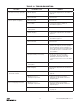
ORDERING INSTRUCTIONS
The following information must accompany all
correspondence orders for replacement parts:
1. Hoist Model Number from identication plate.
2. Serial number of the hoist stamped below
identication plate.
3. Voltage, phase, Hertz from the identication plate.
4. Length of lift.
5. Part number of part from parts list.
6. Number of parts required.
7. Part name from parts list. If trolley replacement parts are
ordered, also include the type and capacity of trolley.
NOTE: When ordering replacement parts, it is
recommended that consideration be given to the need
for also ordering such items as gaskets, fasteners,
insulators, etc. These items may be damaged or lost
during disassembly or just unfit for future use because
of deterioration from age or service
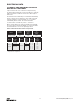
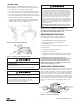
CHAIN STOP INSTALLATION
Place polyurethane stop block over loose end of chain and
slide past desired spot that the chain stop is to be located.
Place one half of chain stop on chain. Then place other half
on top of the rst half of chain stop. (Note: be sure that the
half circle cut out side of one stop block half is aligned with
hex cut out side.) Place one (1) nut into hex cutout insert one
(1) screw with one (1) lock washer through hole opposite nut
and loosely tighten. Repeat for second connection. Tighten
both screw connections to ensure that they do not come
loose.
Hex Cut Out
Loose End
Of Chain
To
Liftwheel
Polyurethane Stop Block
Half-Circle Cut Out
Figure 16. Chain Stop Installation