
User Manual

P/N: 192047082 (REV AA) 627NH January 2018
39
hanging free on loose end side. Make sure the last chain
link is an upstanding link. On double reeved models,
make sure that the new load chain has an even number
of links. On triple reeved models, make sure that the
new chain has an odd number of links. This will prevent
twist in chain. To simplify handling when reassembling
the hoist, a short undamaged piece of the old chain may
be used as a “starter chain”. Position this piece of chain
in exactly the same manner as explained above for the
“new chain”, and complete the reassembly of the hoist.
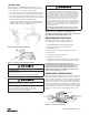
g. Attach the loose end link to chain and connect it to the
hoist frame with the loose end screw, washer and lock
washer, see Figure 7.
h. Set the upper and lower limits before putting the hoist
into service. Refer to the limit switch section.
BE CERTAIN THERE IS NO TWIST.
CAUTION: For double reeved models, be sure to
disconnect one of the loose end links from the load chain
before attaching it to the hoist.
i. For single reeved models, attach the hook block to load
chain and proceed to step K.
j. For double reeved models, run the hoist (UP) until only
3 feet (.9 m) in chain remains on dead end side. This
will minimize the chance of introducing a twist between
hook block and hoist. Allow the chain to hang free to
remove twists. Using a wire as a starter, insert the chain,
at link rst, into lower hook block (upstanding links will
have weld toward sheave) and pull through. Insert last
link into slot in dead end block making sure that no twist
exists in the reeving at any point. Assemble dead end
pin, washer and cotter pin as shown in Figure 7.
k. Using a wire as a starter, insert the chain, at link rst,
into lower hook block (upstanding links will have weld
toward sheave) and pull through. Insert last link into slot
in dead end block making certain that no twist exists in
the reeving at any point. Assemble dead end pin, washer
and cotter pin as shown in Figure 7.
l. Set limit switches as described on page 18. If the new
chain is longer than the old, check to be sure limit switch
will allow for new length of lift. In the event maximum
adjustment does not allow entire length of lift, check
with CM
®
for modication if necessary.
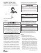
Do not allow hook block to hit hoist or allow load chain to become
taut between loose end screw and frame or else serious damage
will result. If hook block should inadvertently hit the hoist-the
hoist frames, load chain and hook block should be inspected for
damage before further use.
Method #2
Treat the old load chain in hoist as a “starter chain” and
proceed with steps from Method #1, a, b, c and h thru k. If
a starter chain is used, the loose end link (two links required
for double reeved models) can serve as a temporary coupling
link to connect together the starter chain in the hoist and
the new load chain to be installed. Then, under power, reeve
the new load chain through the liftwheel area, replacing the
starter chain in unit. Run enough chain through to attach
loose end link to hoist frame.
Method #3
a. First proceed with Steps 1a, b & c from Method #1.
b. Then, carefully run the load chain out of the hoist.
c. Disconnect hoist from power supply.
d. Remove the electric brake assembly.
e. Rotate the brake hub by hand, at the same time feeding
the load chain into and through liftwheel area with hoist
upside down or using a wire to pull the load chain up
onto the liftwheel as explained in Method #1 step 1f.
f. Refer to Method #1 steps g thru j above to complete
the installation.