
User Manual

P/N: 192047082 (REV AA) 627NH January 2018
38
ASSEMBLY INSTRUCTIONS
SWIVEL HOOK OR LUG SUSPENSION
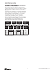
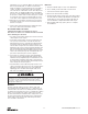
Models E & H. Assemble the dead end bolt and block
through the suspension adapter as shown in Figure 13.
Figure 13. Hook Suspension
FASTENERS
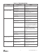
See tables 2a and 2b for recommended torque values.
Using other than CM supplied high strength suspension screws to
attach the suspension adapter to the hoist may cause the screws to
break and allow the hoist and load to fall.
TO AVOID INJURY:
Use only the CM supplied suspension screws to attach the
suspension to the hoist and hand torque these screws to the
recommended seating torque as specied in tables 2a and 2b. DO
NOT apply any type of lubricant to the threads of these screws.
Lubricating the threads will reduce the effort to seat the screws
and as a result, tightening the screws to the above recommended
torque may break the screw,damage the suspension adapter, strip
the nuts and/or damage the hoist frame.
SUSPENSION BOLT SHOULD BE REPLACED ANY TIME
THE SUSPENSION IS REMOVED FROM THE HOIST
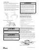
LOWER HOOK BLOCK PIN
When removing or installing the lower hook pin, care must be
taken so as to prevent damaging the pin and/or hook block.
These pins are tapered groove pins and as a result, they
can only be removed in one direction. To remove the pin, a
V-Block, drift and hammer (or slow acting press) are required.
The drift should be the same diameter as the pin (5/16”
diameter (7.94mm) for Models A, AA, B, C, E, F, & H and it
should be placed on the small end of the pin. The small end
of the pin is the end opposite the end on which the 3 grooves
are visible. Place the hook block in the V-Block and drive the
pin out using the drift and a hammer or slow acting press.
To re-install the pin, the parts must be arranged the same
as they were when the pin was removed. To do this, use the
small end of the pin as a gage. First check the holes in the
hook block body and determine which hole is the largest.
Place the hook body in the V-Block with the larger hole on
top. Next, check each end of the hole in the lower hook
chain block and determine which end is the largest. Place the
chain in the slot of the chain block and insert the chain block,
with the large hole on top, into the hook block body. Align the
holes in the hook block body with the hole in the chain block
and insert the small end of the pin in the hole. Push the pin in
by hand until it stops and then use a hammer or slow acting
press to drive the pin into position so that the end of the pin
is ush with the outside surface of the hook block body.
Use of improper lower hook chain block pin as well as improper
installation of this pin can cause the pin to break and allow the
load to fall.
TO AVOID INJURY:
Use only CM supplied, special high strength lower hook chain
block pin to attach the chain to the lower hook block and install
the pin as directed above.
REMOVAL AND INSTALLATION OF LOAD CHAIN
Improper installation (reeving) of the load chain can result in a
dropped load.
TO AVOID INJURY/DAMAGE:
• Verify use of proper size and type of hoist load chain for
specic hoist.
• Install load chain properly as indicated below.
NOTE: When installing load chain in Models E & H by
either of the “starter chain” methods, two loose end
connecting links (627-743) must be used. Hoist load
chain can be installed by any one of several methods.
USE OF COMMERCIAL OR OTHER MANUFACTURER’S CHAIN AND
PARTS TO REPAIR CM HOISTS MAY CAUSE LOAD LOSS.
TO AVOID INJURY:
Use only CM supplied replacement load chain and parts. Chain
and parts may look alike, but CM chain and parts are made of
specic material or processed to achieve specic properties.
The rst method is recommended when replacing severely
worn load chain and requires disassembling the hoist.
Method 2 does not require hoist disassembly, where as
Method 3 requires only partial disassembly.
Method #1
a. Disconnect hoist from power supply.
b. Disable the electronic limits. Refer to the limit
switch section.
c. Detach loose end of load chain from hoist frame, see
Figure 7. Also, on single reeved models, detach the
lower hook block from the load chain. On double reeved
models E & H unfasten the dead end side of load chain.
d. Continue to disassemble the hoist and inspect the
liftwheel, chain guides, motor housing and gear housing
which if worn or damaged may cause premature failure
of the new chain. Parts can be easily identied by
referring to pages Parts List section of table of contents.
e. If the liftwheel pockets, in particular the ends, are worn
or scored, replace liftwheel. If chain guides and housing
are worn, cracked or damaged these parts should also
be replaced.
f. Reassemble hoist with the new load chain inserted over
the liftwheel. Position chain with the weld on up standing
links away from liftwheel and leave only one foot of chain
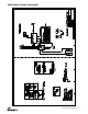
4.25in
(108mm)
Models E & H