
User Manual


P/N: 192047082 (REV AA) 627NH January 2018
18
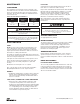
LIMIT SWITCH (EPLS) ADJUSTMENTS
If limit switch operation has been checked as described on
page 12 and is not operating correctly or is not automatically
stopping the hook at a desired position, proceed as follows:
1. Disconnect hoist from power supply.
2. Remove the back frame cover.
3. Reconnect the hoist to the power supply.
SETTING UPPER LIMIT SWITCH
1. The "A" Dimensions given in Table 11 are the minimum
distance that should be set between the top at hook
block and the bottom of the hoist.
2. Operate the hoist in the up direction until the hook block
is at the desired upper limit position. CAUTION: actual
limit position may vary from initial set position. See
dimension "C" in table 11.
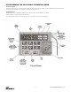
3. Navigate to parameter C3.12 of the VFD (see
programming section).
4. Change the value to "2" and press enter.
5. Exit programming mode.
6. Check upper limit function and position. If adjustment
is desired, refer to the "C" dimension to determine the
minimum adjustment from the current setting.
7. Repeat steps 2-6 as necessary to achieve desired
limit position.
8. Set lower limit.
CAUTION: THE “A” DIMENSIONS ARE THE MINIMUM
ALLOWED FOR SAFE OPERATION AND SHOULD
NOT BE REDUCED.
SETTING LOWER LIMIT SWITCH
1. Refer to Table 6 -The“B” dimensions given are the
minimum length of loose end chain left on the non-load
side of the liftwheel when the hook is positioned at the
lowest allowable hook position.
2. Operate the hoist in the down direction until the hook
block is at the desired lower limit position. CAUTION:
actual limit position may vary from initial set position. See
dimension "C" in table 11.
3. Navigate to parameter C3.12 of the VFD (see
programming section).
4. Change the value to "3" and press enter.
5. Exit programming mode.
6. Check lower limit function and position before placing the
unit into service. If adjustment is desired, refer to the "C"
dimension to determine the minimum adjustment from
the current setting.
7. Repeat steps 2-6 as necessary to achieve desired
limit position.
8. Disconnect the hoist from the power supply.
9. Re-install the end cover.
CAUTION: THE “B” DIMENSIONS ARE THE
MINIMUM ALLOWED FOR SAFE OPERATIONS
AND SHOULD NOT BE REDUCED.
SLOW APPROACH
The Lodestar VS slow approach function will automatically
slow down to 1/3 of normal 60Hz speed when the hook
approaches one of the hook travel limits. This offers
operators a warning that they are approaching the nal
hoist limit. This feature is enabled by default from the
factory. This feature can be enabled or disabled by
setting C03-22 to 1 or 0, respectively.
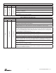
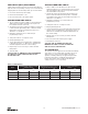
Table 11. Limit Switches
Models
A (minimum distance between top of hook
and bottom of hoist)
B (minimum distance between top of loose
end chain stop and bottom of hoist)
C (increment between available limit set
positions)
in mm in mm in mm
A, C
3 76.2 3 76.2 2 50.8
AA 6 152.4 6 152.4 3.75 95.25
B, F 1.5 38.1 1.5 38.1 1 25.4
E, H 1.5 38.1 1.5 38.1 0.5 12.7