
User Manual


P/N: 192047082 (REV AA) 627NH January 2018
12
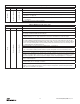
Table 5. Minimum Wire Size
Length of
Extension Cord
Minimum Wire Size
UP TO 200 FEET #14 AWG
BEYOND 200 FEET CONTACT FACTORY
Failure to provide a proper power supply system for the hoist may cause
hoist damage and offers the potential for a re.
TO AVOID INJURY:
Provide each hoist with a 20 amp, minimum, overcurrent
protected power supply system per the National Electrical Code
and applicable local codes as instructed in this manual.
Remember, operation with low voltage can void the CM
repair/replacement policy. When in doubt about any of the
electrical requirements, consult a qualied electrician.
Working in or near exposed energized electrical equipment presents the
danger of electric shock.
TO AVOID INJURY:
DISCONNECT POWER AND LOCKOUT/TAGOUT
DISCONNECTING MEANS BEFORE REMOVING COVER OR
SERVICING THIS EQUIPMENT.
CHECKING LIMIT SWITCH (EPLS) OPERATION
The limit switch will automatically stop the hook at any
predetermined point when either hoisting or lowering.
Allowing the hook block to run into the bottom of the hoist when raising
a load or allowing the chain to become taut between the loose end
screw and the frame when lowering a load may break the chain and
allow the load to drop.
Do not allow the hook block to contact the bottom of the
hoist or the loose end chain to become taut.
Operate hoist over the entire length of its rated lift, checking
upper and lower limit switches for correct operation as
follows:
4. Press (UP) control and raise the lower hook until top of
hook block is about one foot (305 mm) below the hoist.
5. Cautiously continue raising the hook until the upper limit
switch stops the upward motion. The upper limit switch
is set at the factory to stop the hook block 3 inches (76.2
mm) from bottom of the hoist on all units with standard
10 foot (3m) lift except Model AA. Factory setting is 6
inches (152.4 mm) for this model and for all other models
equipped with chain for lifts longer than 10 feet (3m).
6. If adjustment is necessary, see page 18.
7. Press (DOWN) control and cautiously lower hook until
lower limit switch stops the downward motion From 7
to 11 chain links (depending on hoist model) should
be between the loose end link and the hoist entry.
See Figure 7.
8. If adjustment is necessary, see page 18.
NOTE: If the hoist is equipped with a chain container/
bag, reset the upper and lower limit switches as
indicated on page 18.
Under no condition should the hook block or load
be permitted to come in contact with the chain
container/bag. If contact is made, the function of
the chain container can be interfered with and its
fasteners imperiled.
NOTE: When chain bag is filled to capacity the bag
must be no more than 75% filled.
NOTE: If the hoist gears ever rotate without encoder
input to the drive, either due to encoder or wiring
failure, or due to maintenance or disassembly of the
hoist, the limits must be reset as described on page 18.
CONTROL CORD
Unless ordered on a special basis, the hoist is supplied
with a control cord that will position the control station
approximately 4 feet above the lower hook when it is at
the lower limit of the lift. If this places the control station
too close to the oor, a “control cord alteration kit”
(Part Number 28642) can be obtained from CM for
shortening the length of the control cord.
Tying knots or loops to shorten the drop of the control station will make the
strain relief ineffective and the internal conductors of the cord may break
TO AVOID INJURY:
Shorten the control cord using the control cord alteration kit
and the instructions provided with the kit.
OPERATING INSTRUCTIONS
GENERAL
1. The Load-limiter is designed to slip on an excessive
overload. An overload is indicated when the hoist will
not raise the load. Also, some clutching noise may be
heard if the hoist is loaded beyond rated capacity.
Should this occur, immediately release the (UP) control
to stop the operation of the hoist. At this point, the load
should be reduced to the rated hoist capacity or the
hoist should be replaced with one of the proper capacity.
When the excessive load is removed, normal hoist
operation is automatically restored.
CAUTION: The Load-limiter is susceptible to
overheating and wear when slipped for extended
periods. Under no circumstance should the clutch
be allowed to slip for more than a few seconds.
It is not recommended for use in any application where
there is a possibility of adding to an already suspended
load to the point of overload. This includes dumbwaiter
(*see below) installations, containers that are loaded in
mid-air, etc.
(*) Refer to limitations on Page 3 concerning dumbwaiter
applications.
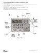
2. All hoists are equipped with electronically programmable
limit switches, which automatically stops the hook at any
predetermined point when either hoisting or lowering.
3. Rated lifting speeds are shown on hoist identication
plate. SLOW speed is intended as a means of carefully
controlling or “spotting” the load, although the hoist
may be operated solely at this speed if desired. It is not
necessary to operate in the SLOW speed position as the
hoist will pick up a capacity load at FAST speed from
a standing start. In other words, it is not necessary to