
User Manual


P/N: 192047082 (REV AA) 627NH January 2018
11
THREE PHASE HOIST
All Lodestar VS hoists operate on 3 phase power.
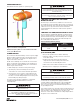
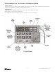
Figure 8. Location of Components
Variable Frequency Drive is located under back frame
cover (1) for Models A-H.
POWER PHASING
The Lodestar VS will automatically correct for power supply
phasing. If after a repair the hoist is running in the wrong
direction, it should be corrected by correcting the motor
output connections at the VFD.
NOTE: Serious damage can result if the hook is run to the
upper or lower limit of travel with the hook operating in a
direction opposite to that indicated by the control station.
Therefore, proceed as follows:
1. Make temporary connections at the power supply.
2. Operate (UP) control momentarily. If hook raises,
connections are correct and can be made permanent.
3. If hook lowers, it is necessary to change direction by
correcting the motor output connections (T1,T2,T3) at
the VFD. Consult the wiring diagram. Disconnect power
before making any wiring changes.
Do not force the Lodestar Load-limiter to compensate
for improperly adjusted limit switches or reverse
voltage phasing.
Working in or near exposed energized electrical equipment presents the
danger of electric shock.
TO AVOID INJURY:
DISCONNECT POWER AND LOCKOUT/TAGOUT
DISCONNECTING MEANS BEFORE REMOVING COVER OR
SERVICING THIS EQUIPMENT.
Allowing the hook block to run into the bottom of the hoist when raising
a load or allowing the chain to become taut between the loose end
screw and the frame when lowering a load may break the chain and
allow the load to drop.
TO AVOID INJURY:
Do not allow the hook block to contact the bottom of the hoist or
the loose end chain to become taut.
CHECKING FOR TWIST IN LOAD CHAIN
MODELS E AND H.
The best way to check for this condition is to run the lower
hook, without a load, up to within about 2 feet (.61 meters) of
hoist. If the dead end of the chain has been properly installed,
a twist can occur only if the lower hook block has been
capsized between the strands of chain. Reverse capsize to
remove twist.
CHECKING FOR ADEQUATE VOLTAGE AT HOIST
The hoist must be supplied with adequate electrical power in
order to operate properly. For proper operation, the voltage,
(measured at the hoist end of the standard power cord with
the hoist operating in the, up direction with full load) must
be as indicated in the table below.
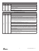
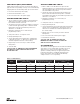
Table 4. Minimum Running Voltage
Nominal Voltage
Minimum
Running Voltage
230VAC 170VAC
460VAC 323VAC
SIGNS OF INADEQUATE ELECTRICAL POWER
(LOW VOLTAGE) ARE:
• Noisy hoist operations due to brake chattering.
• Dimming of lights or slowing of motors connected
to the same circuit.
• Heating of the hoist motor and other internal
components as well as heating of the wires and
connectors in the circuit feeding the hoists.
• Failure of the hoist to lift the load due to motor stalling.
• Blowing of fuses or tripping of circuit breakers.
Failure to properly ground the hoist presents the danger of
electric shock.
TO AVOID INJURY:
Permanently ground the hoist as instructed in this manual.
To avoid these low voltage problems, the hoist must be
connected to an electrical power supply system that
complies with the National Electrical Code and applicable
local codes. This system must also provide (slow blow
fuses or inverse-time type circuit breakers) and provisions
for grounding the hoist.
Low voltage may also be caused by using an undersized cord
and/or connectors to supply power to the hoist. The following
chart should be used to determine the size wires in the
extension cord in order to minimize the voltage drop between
the power source and the hoist.