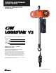
OPERATING, MAINTENANCE & PARTS MANUAL VARIABLE SPEED ELECTRIC CHAIN HOIST Before installing hoist, fill in the information below. Model Number Serial No. Purchase Date Voltage Rated Load RATED LOADS 1/8 TO 1 TONNES 125 KG TO 1000 KG Follow all instructions and warning for inspecting, maintaining and operating this hoist. The use of any hoist presents some risk of personal injury or property damage. That risk is greatly increased if proper instructions and warnings are not followed.
CM HOIST PARTS AND SERVICES ARE AVAILABLE IN THE UNITED STATES AND IN CANADA PARTS FOR YOUR HOIST ARE AVAILABLE FROM YOUR LOCAL AUTHORIZED REPAIR STATION. FOR THE NAME OF THE NEAREST PARTS OR SERVICE CENTER, VISIT OUR WEB SITE WWW.CMWORKS.COM OR CALL OUR CUSTOMER SERVICE DEPARTMENT.
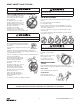
Usage of hoists that do not involve lifting of the load on the lower hook or using hoists in the inverted position without special precaution may cause an accident resulting in injury and/or property damage Improper operation of a hoist can create a potentially hazardous situation which, if not avoided, could result in minor or moderate injury. To avoid such a potentially hazardous situation, the operator shall: TO AVOID INJURY: 1. Maintain a firm footing or be otherwise secured when operating the hoist.
HOIST SAFETY IS UP TO YOU... DO NOT LIFT MORE THAN RATED LOAD. DO NOT PULL AT AN ANGLE. BE SURE HOIST AND LOAD ARE IN A STRAIGHT LINE. CHOOSE THE RIGHT HOIST FOR THE JOB... DO NOT USE LOAD CHAIN AS A SLING. Choose a hoist with the capacity for the job. Know the capacities of your hoists and the weight of your loads. Then match them.
FOREWORD This manual contains important information to help you properly install, operate and maintain your hoist for maximum performance, economy and safety. Please study its contents thoroughly before putting your hoist into operation. By practicing correct operating procedures and by carrying out the recommended preventive maintenance suggestions, you will experience long, dependable and safe service.
GENERAL INFORMATION CM REPAIR/REPLACEMENT POLICY All Columbus McKinnon (CM®) Lodestar Electric Chain Hoists are inspected and performance tested prior to shipment. If any properly maintained hoist develops a performance problem due to a material or workmanship defect, as verified by CM®, repair or replacement of the unit will be made to the original purchaser without charge.
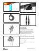
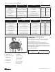
Figure 1. Chain Container Figure 5. UT Trolley Figure 2. Latchlok Hook Figure 6. CM® Rocket™ Universal Pendant Control ACCESSORIES HOOK SUSPENSIONS Swivel and rigid type hook suspensions are available for all Lodestar Electric Hoists. However, rigid type hook suspensions are normally recommended for most application.
LUG SUSPENSION Lug suspensions are available for all Lodestar Electric Hoists. These are rigid type suspensions wherein the lug shown replaces the hook in the suspension adapter. The Lug suspensions are required for suspending the hoist from the Series 635 Low Headroom, Motor Driven, Universal Trolleys described next. SERIES 635 LOW HEADROOM TROLLEY These are manual push type trolleys (see Figure 3) designed for use with the Lodestar Electric Chain Hoists.
INSTALLATION UNPACKING INFORMATION Using other than CM supplied high strength suspension screws to attach the suspension adapter to the hoist may cause the screws to break and allow the hoist and load to fall. When received, the hoist should be carefully inspected for damage which may have occurred during shipment or handling.
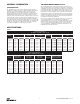
Table 2a. Torque Specification: All Models Fastener Fastener Description Tool Required Brake End Cover 1/4"-20 Socket Head Cap Screw Motor End Cover *Recommended Seating Torque ft-lbf N-m 3/16" Hex Driver 4.2 - 5.0 5.7 - 6.8 1/4"-20 Socket Head Cap Screw 3/16" Hex Driver 4.2 - 5.0 5.7 - 6.8 1/4-20 Button Head Screw for Miscellaneous Applications 1/4-20 Button Head Socket Cap Screw 5/32" Hex Driver 4.2 - 5.0 5.7 - 6.8 Cord Grips ø3/4" NPT Cord Grip 1-1/16" Hex Socket or Wrench 5.0 - 5.
THREE PHASE HOIST All Lodestar VS hoists operate on 3 phase power. Allowing the hook block to run into the bottom of the hoist when raising a load or allowing the chain to become taut between the loose end screw and the frame when lowering a load may break the chain and allow the load to drop. TO AVOID INJURY: Do not allow the hook block to contact the bottom of the hoist or the loose end chain to become taut. CHECKING FOR TWIST IN LOAD CHAIN MODELS E AND H.
U nder no condition should the hook block or load be permitted to come in contact with the chain container/bag. If contact is made, the function of the chain container can be interfered with and its fasteners imperiled. Table 5. Minimum Wire Size Length of Extension Cord Minimum Wire Size UP TO 200 FEET #14 AWG BEYOND 200 FEET CONTACT FACTORY N OTE: When chain bag is filled to capacity the bag must be no more than 75% filled.
which could result in twisted chain and a jammed liftwheel. hesitate at the slow position when moving control from STOP to FAST position or vice versa. 4. If material being handled must be immersed in water, pickling baths, any liquid, dusty or loose solids, use a sling chain of ample length so that the hook is always above the surface. Bearings in the hook block are shielded only against ordinary atmospheric conditions. b. The upper limit switch is by-passed and the load could hit the hoist. c.
INSPECTION NYLON THREAD LOCKING NUTS - It is not necessary to replace the nylon thread locking nuts each time the suspension bolts are replaced as long as new bolts with the locking patch are being used. It is recommend that the nylon thread locking nuts are replaced each time the hoist is torn down to allow these nuts to be replaced. To maintain continuous and satisfactory operation, a regular inspection procedure must be initiated to replace worn or damaged parts before they become unsafe.
Table 7. Minimum Frequent Inspections TYPE OF SERVICE ITEM Severe a) Brake for evidence of slippage. Daily to Weekly Heavy Weekly to Monthly Monthly Normal b) Control functions for proper operation. c) Hooks for damage, cracks, twists, excessive throat opening, latch engagement and latch operation - see page 14. d) Load chain for adequate lubrication, as well as for signs of wear, damaged links or foreign matter - see page 17. e) Load chain for proper reeving and twists. Table 8.
INSPECTING THE LOAD CHAIN: The chain must be inspected at regular intervals, with a minimum of once annually. As the frequency of use increases, the time intervals between inspections must be reduced. During inspection, the chain must be examined along their entire length, including the hidden parts.
MAINTENANCE LOAD CHAIN A small amount of lubricant will greatly increase the life of load chain. Do not allow the chain to run dry. LOAD-LIMITER The Load-limiter should operate for the normal life of the hoist without service. The device has been calibrated at the factory for a specific model of hoist. For proper overload protection, be sure before installing a Load-limiter that it is correct for the unit.
LIMIT SWITCH (EPLS) ADJUSTMENTS SETTING LOWER LIMIT SWITCH If limit switch operation has been checked as described on page 12 and is not operating correctly or is not automatically stopping the hook at a desired position, proceed as follows: 1. Refer to Table 6 -The“B” dimensions given are the minimum length of loose end chain left on the non-load side of the liftwheel when the hook is positioned at the lowest allowable hook position. 1. Disconnect hoist from power supply. 2.
PROGRAMMING THE ADJUSTABLE FREQUENCY DRIVE Using The Keypad All functions of the drive are accessed using the keypad. The information needed to configure the drive’s application is entered into the drive by using the functional LEDs. This information is stored into the drive’s memory. Keypad Functions The keypad has a 5-digit LED display. Both numeric and alpha-numeric data can appear on the display. Indicators and keys on the keypad are described below.
KEYPAD LED AND BUTTON FUNCTIONS Some of the keypad buttons, whose functions are described below, are dual-purpose. The dual- purpose keys have one function when used in a view-only mode and another function when used in a programming mode.: KEYS AND DISPLAYS ON THE LED OPERATOR NO. DISPLAY NAME FUNCTION 1 Data Display Area Displays the frequency reference, parameter number, etc.
FUNCTION LEDS NO. Display Lit Flashing OFF When an alarm occurs 12 When the drive detects an alarm or error OPE detected Normal state (no fault or alarm) When a fault or error occurs during Auto-TUning 13 When the REVERSE command is given — When the FORWARD command is given 14 Drive Ready Auto-Tuning — Programming Mode 15 Displays output frequency (Hz) — — PARAMETERS There are hundreds of parameters, organized by function group, that determine how the drive functions.
IMPULSE•G+ MINI STRUCTURE OF PARAMETERS Frequency Reference Setting Sets/Displays the drive operation speed (Hz). Output Frequency Monitor Displays the output frequency (Hz.) at which the drive is currently operating. This is a monitor only function; the operator cannot change the displayed value by use of the keypad. Output Current Monitor Displays the level of output current (Amps) that the drive is currently producing.
MONITOR PARAMETERS PARAMETER CODE NAME FUNCTION UNITS MONITOR U01.01 Frequency Reference Frequency Reference Hz U01.02 Output Frequency Inverter Output Frequency Hz U01.03 Output Current Inverter Output current A U01.04 Control method Displays the value of A01.02 — — U01.05 Motor Speed Motor Speed (OLV only) U01.06 Output Voltage Inverter Output Voltage (Reference) V U01.07 DC Bus Voltage DC Bus Voltage (Measured) V U01.
MONITOR PARAMETERS Parameter Code Name Function Units Monitor U01.13 Elapsed Time Elapsed Time hours U01.14 Flash ID Flash ROM software ID number -- U01.15 Terminal A1 Level External Terminal input level V U01.16 Terminal A2 Level External Terminal input level V/mA U01.20 Output Frequency after Soft Start --- Hz U01.28 Software CPU --- -- U01.34 OPE Detection Parameter Parameter OPE detected const # U01.
MONITOR PARAMETERS Parameter Code Name Function Units Fault Trace U02.13 Operation Status @ Fault Inverter status before fault was detected -- U02.14 Elapsed Time @ Fault Elapsed time when fault was detected hr U02.15 Speed Reference During Soft Start @ Fault Speed reference during soft start at previous fault % U02.16 Motor q-Axis Current During Fault --- -- U02.17 Motr d-Axis Current During Fault --- -- Fault History U03.01 Last Fault Displays most recent fault -- U03.
MONITOR PARAMETERS Parameter Code Name Function Units Maintenance U04.09 LED Check Lights all segments of the LED to verify that the display is working properly U04.10 kWh: Lower 4 Digits -- U04.11 kWh: Upper 5 Digits -- U04.12 CPU Resources Used -- U04.13 Peak Hold Current -- U04.14 Peak Hold Output Frequency -- U04.16 Motor Overload (oL1) Detection Level --- U04.17 Motor Overload (oL2) Detection Level U04.18 Frequency Reference Source Selection -- U04.
IMPULSE G+MINI ADJUSTABLE FREQUENCY DRIVE SPECIFICATIONS Specification Specification Value and Information for all Models Certification UL, cUL, CE, TüV, RoHS Rated input power supply volts & frequency 3-phase 200~240V or 380~480V: 50/60 Hz Allowable input voltage fluctuation +10% or -15% of nominal Allowable input frequency fluctuation ±5% of nominal Control method Fully digital; sine-wave, pulse-width-modulated Maximum output voltage (VAC) Max output voltage 3-phase, 200~240V; 380~480V (propo
SPEED CONTROL METHODS The IMPULSE.G+Mini provides 1-step, 2-step or 3-step Multi-Step control methods. For each input that is energized, the drive begins to operate at the corresponding frequency. If 1, 2 or 3-step is desired, then the frequency reference for the 1st, 2nd or 3rd step will be set at the maximum desired speed of operation. In addition to discrete speed control, true infinitely variable speed control can be configured. The IMPULSE.
FACTORY SETTINGS OF PARAMETERS Control 2-Step/2-Speed and 3-Step/3-Speed 2-Step/3-Step Infinitely Variable Parameter Setting B01.01 - First Speed (Hz) 10 Hz B01.02 - Second Speed (Hz) 30 Hz (2 Speed: 60 Hz) B01.03 - Third Speed (if equipped, Hz) 60 Hz B05.01 - Acceleration Time (seconds) 1 second B05.02 - Deceleration Time (seconds) 1 second C03.12 - EPLS (see page 18) 1 (enabled) C03.22 - Slow Approach (see page 18) 1 (enabled) C06.01 - Swift-Lift (see page 27) 1 (enabled) B01.
FACTORY SETTINGS OF PARAMETERS Fault Code Fault or Indicator Name/Description Corrective Action BB (flashing) Base Block External Base Block Indicator. The flashing base block signal is the result of a multi function input in the terminal strip. The base block indicates that the drive’s IGBTs have been disabled. The motor will begin coasting when the base block input is received.
CPF22 A/D Conversion Fault. A/D conversion error. 1. Cycle power to the drive. 2. Ensure that the control board terminals and wiring are shielded from electrical noise. 3. Replace the drive. CPF23 PWM Feedback Fault. PWM feedback error. 1. Cycle power to the drive. 2. Replace the drive. CPF24 Drive Capacity Signal Fault. Entered a capacity that does not exist (checked when the drive is powered up.) 1. Cycle power to the drive. 2. Replace the drive. CRST Cannot reset.
LL1 (flashing) Lower Limit 1 Err Lower Limit 1-SLOW Down Indicator. Hoist has reached lower slow approach limit. No action is required. If desired, slow approach limits may be disabled as described on page 18. 1. May not require corrective action. 2. Check the position of the Limit Switch. LL2 (flashing) Lower Limit 2 Err Lower Limit 2-STOP Indicator. Hoist has reached lower limit. Run hoist UP away from lower limit, or if limit is in an inappropriate place, reset limits as described on page 18. 1.
OT2 Overtorque Det 2 Overtorque Detection Level 2 Fault. Defined by L06.05. Alarm defined by L06.04. 1. Check for proper programming for L06.XX constant. OV DC Bus Overvolt Overvoltage Fault. The DC bus voltage exceeded for overvoltage level. Detection level: 230V class-approximate 410V 460V class-approximate 820V 1. Extend the deceleration time. 2. Check for proper DBU operation. 3. Check the resistor. 4. Check the line voltage. 5. If on a load break hoist, check the gear box.
TABLE 12. TROUBLESHOOTING TROUBLE 1. Hook does not respond to the control station or control device PROBABLE CASE REMEDY A.) No voltage at hoist-main line or branch circuit switch open; branch line fuse blown or circuit breaker tripped. A.) C lose switch, replace fuse or reset breaker. B.) Phase failure (single phasing, three phase unit only)-open circuit, grounded or faulty connection in one line of supply system, hoist wiring, reversing contactor, motor leads or windings. B.
TABLE 12. TROUBLESHOOTING TROUBLE 6.) Hook does not stop promptly. 7.) Hoist operates sluggishly. 8.) Motor overheats. 9.) Hook fails to stop at either or both ends of travel. 10.) Hook stopping point varies. PROBABLE CASE REMEDY A.) B rake slipping. A.) Check brake adjustment as described on page 17. B.) Excessive load. B.) S ee item 1H. A.) Excessive load. A.) See item 1H. B.) Low voltage. B.) C orrect low voltage condition as described on page 11. C.
ELECTRICAL DATA TO DETECT OPEN AND SHORT CIRCUITS IN ELECTRICAL COMPONENTS Open circuits in the coils of electrical components may be detected by isolating the coil and checking for continuity with an ohmmeter or with the unit in series with a light or bell circuit. Shorted turns are indicated by a current draw substantially above normal (connect ammeter in series with suspected element and impose normal voltage) or D.C. resistance substantially below normal.
8 3 CORRECTED WIRE NUMBERS 1/9/2018 2 Standard Dimensional Tolerances Unless Otherwise Specified Dimensional Units INCH Description: Columbus McKinnon Corporation Hoist & Rigging - Americas Amherst, NY USA 1 37 A B C AB AA Rev.
ASSEMBLY INSTRUCTIONS by hand until it stops and then use a hammer or slow acting press to drive the pin into position so that the end of the pin is flush with the outside surface of the hook block body. SWIVEL HOOK OR LUG SUSPENSION Models E & H. Assemble the dead end bolt and block through the suspension adapter as shown in Figure 13. Use of improper lower hook chain block pin as well as improper installation of this pin can cause the pin to break and allow the load to fall.
hanging free on loose end side. Make sure the last chain link is an upstanding link. On double reeved models, make sure that the new load chain has an even number of links. On triple reeved models, make sure that the new chain has an odd number of links. This will prevent twist in chain. To simplify handling when reassembling the hoist, a short undamaged piece of the old chain may be used as a “starter chain”.
CUTTING CHAIN CM® Load chain is hardened and it is difficult to cut. The following methods are recommended when cutting a length of new chain from stock or cutting off worn chain. Testing Before using, all altered, repaired or used hoists that have not been operated for the previous 12 months shall be tested by the user for proper operation. First test the unit without a load and then with a light load of 22.7 kg.
MODELS A, AA, B, C, E, F & H 41 P/N: 192047082 (REV AA) 627NH January 2018
MODELS A, AA, B, C, E, F & H Item No.
MODELS A, AA, B, C, E, F & H (CONT.) Item No. Description Model A Model AA Model B Model C Model E Model F Model H Qty 31 ROD, 1/4-20 X 3.50 THREADED 192045461 3 32 ROD, FOAM RUBBER, Ø.125 X 1.57 192045457 1 33 ROD, FOAM RUBBER, Ø.125 X .
MODELS A, AA, B, C, E, F & H 44 P/N: 192047082 (REV AA) 627NH January 2018
MODELS A, AA, B, C, E, F & H Item No. Part No. Description 192045986 1 192045990 COMPLETE GEARBOX ASS'Y 192045994 Models A & C Model AA Models B, E, F & H 1 - - - 1 - - - 1 1.1 00000504C V1 MOTOR HSG S/A-ORANGE 1 1 1 1.2 10001591 LIFTWHEEL S/A - V1 1 1 1 1.3 10001354 O-RING BUNA-N AS568A-122 1 1 1 1.4 10001388 O-RING BUNA-N 1.5MM X 27MM ID 1 1 1 1.5 10001110 V1 CHAIN GUIDE COATED 2 2 2 1.6 82354 1/4 DOWEL PIN 4 4 4 1.
UPPER SUSPENSIONS 1.2 1.2 1.6 1.11 1.11 1.6 1.2.1 1.11 1.11 1.4 1.1 1.5 1.1 1.3 1.10 1.4 1.5 1.8 1.9 1.10 LUG ASSEMBLY 1.7 1.9 1.7 1.8 1.16 1.13 SWIVEL HOOK ASSEMBLY 1.12 1.15 1.14 1.2 1.2 1.17 3 1.11 1.1 1.2.1 1.11 1.6 1 1.11 1.5 1.1 1.4 2.6 2.5 2.4 1.4 1.5 2.2 1.8 2.3 2 2.1 2.10 1.10 1.9 1.7 2.7 2.9 2.
UPPER SUSPENSIONS Part Numbers Item No. Description SWIVEL SUSPENSION ASSEMBLY - W/ LATCH TYPE HOOK 1 1.1 1.2 1.2.1 1.3 1.4 1.
UPPER SUSPENSIONS UNIVERSAL TROLLEY MODELS A, AA, B, C, E, F & H Item No.
LOWER HOOK BLOCKS SINGLE REEVED 1.8 1.7 1.6 1.5 1.4 1.3 1.2 1.1.1 1.1 Item No. Models A, AA, B, C & F Qty. LOWER HOOK BLOCK ASSEMBLY-COMPLETE WITH LATCH TYPE HOOK *28683 1 LOWER HOOK WITH LATCH 28686 1 LATCHLOK TYPE HOOK 28604 1 LATCH KIT 45661 1 1.2 LOWER HOOK BODY 45401B 1 1.3 LOWER HOOK WASHER 945921 1 1.4 LOWER HOOK THRUST BEARING 88485 1 1.5 LOWER HOOK NUT 982526 1 1.6 LOWER HOOK NUT PIN 983772 1 1.7 LOWER HOOK CHAIN BLOCK 28007 1 1.
LOWER HOOK BLOCKS DOUBLE REEVED 1.4 1.3 1.4 1.3 1.8 1.2 1.2 1.4 1.4 1.9 1.7 1.2 1.6 2 1.7 1.1.3 1.9 1.1.2 1.1.1.1 1.5 1.1.1 1.7 1.10 1.1.1.1 1.1 1.1.5 DOUBLE-REEVED LOWER HOOK BLOCKS DOUBLE REEVED Item No. Decription Models E & H Qty. 1 LOWER HOOK BLOCK ASSEMBLY-COMPLETE WITH LATCH TYPE HOOK *00000272B 1 LOWER HOOK ASSEMBLY WITH LATCH AND BRG 28665 1 LATCHLOK TYPE HOOK ASSEMBLY WITH BRG – 1 LOWER HOOK WITH LATCH 28687B 1 1.1 1.1.1 LATCHLOK TYPE HOOK 28603 1 1.1.1.
DC BRAKE A, AA, B, C, E, F & H Item No. Part Number Description Qty. 1 10001309 SPACER 1 2 00001432 HUB SPACER V1 DC BRAKE 1 3 192042811 HUB, BRAKE #6, INTORQ 1 4 10409710 ROTOR CLIP RETAINING RING 1 5 192042664 BRAKE, 205VDC, #6 INTORQ 1 5.1 192043933 FRICTION PLATE 1 5.2 192043932 FRICTION DISC (ROTOR) 1 5.3 192043930 SCREW, M4 X 50 SHCS 3 5.
BACKFRAME COVER ASSEMBLY MODELS A, AA, B, C, E, F & H Item No. Part Number Description Qty. 1 192046013 BRAKE COVER-V1 SIA - ORANGE 1 1.1 192042382 ENDCOVER, V1 BRAKE, MACH., ORANGE 1 1.2 192043818 RESISTOR, DB, 200W, 150 OHM 2 2 1.3 192043819 THERMAL PAD 1.4 192045463 SCREW, HEX HEAD,8-32 THRO FRMNG 4 1.5 192045454 INSULATING TAPE APPROX. 12.25" 1.6 192045458 JUMPER - DBR LEAD 2 1.7 192045459 JUMPER - DBR 1 1.8 192045460 LANYARD, LOOP TO 90°EYE, 8" 2 1.
COMPLETE CONTROL CORD AND STATION ASSEMBLY VFD, 2-SPEED HOIST CONTROL STATION 1.1 1.2 1.1.2 1.1.4 1.1.2 1.1.2 1.1.1 1.1.3 1.1.4 1.1.5 1.1.4 Item No. 1 1.1 Part Number Description Qty. 23659706 STATION ASSEMBLY AND CONTROL CORD FOR 10 FOOT LIFT 23659711 STATION ASSEMBLY AND CONTROL CORD FOR 15 FOOT LIFT 23659716 STATION ASSEMBLY AND CONTROL CORD FOR 20 FOOT LIFT 58273 2 BUTTON CONTROL STATION 1 1 1.1.1 58278 GROMMET 1 1.1.2 58275 HARDWARE KIT 1 1.1.
COMPLETE CONTROL CORD AND STATION ASSEMBLY VFD, 3-SPEED HOIST CONTROL STATION 1.1 1.2 1.1.2 1.1.4 1.1.2 1.1.2 1.1.3 1.1.1 1.1.4 1.1.5 1.1.4 Item No. 1 1.1 Part Number Description Qty. 23659806 STATION ASSEMBLY AND CONTROL CORD FOR 10 FOOT LIFT 23659811 STATION ASSEMBLY AND CONTROL CORD FOR 15 FOOT LIFT 23659816 STATION ASSEMBLY AND CONTROL CORD FOR 20 FOOT LIFT 58296 2 BUTTON CONTROL STATION 1 1 1.1.1 58278 GROMMET 1 1.1.2 58275 HARDWARE KIT 1 1.1.
CM ROCKET UNIVERSAL PENDANT CONTROL 23 20 29 28 2 3 17 24*** 27 14 6* 13** 27 16 29 19 27 16 10 7 12 4 25 15 5 18 26**** ** Strain Relief Plate *** 2-Speed Pendants include 4 Switches **** Screw Terminal Strip 24 13 29 26 19 Product Code Description Product Code Description ECUR-0001 Strain Relief Kit ECUR-1S Rocket Pendant Control - Single-Speed, No E-stop ECUR-0010 Switch Repair Kit, 2-Speed, 4 Switch Rocket Universal Pendant Control ECUR-2S Rocket Pendant Control -
5" METAL AND FABRIC CHAIN CONTAINER INSTALLATION INSTRUCTIONS 10 9 USE HOLE B FOR MODELS J THRU RRT-2 Item 7: THIS TAB IS BENT UP TO HORIZONTAL TO SECURE HHCS (HEX HEAD CAP SCREW) B 2 A 3 5 USE HOLE A FOR MODELS A THRU H-2 1 6 7 8C 8B 8A 4 Chain Container Bucket Length Vs.
LUBRICANTS Part Number for Packaged Lubricants Used in the Lodestar Electric Chain Hoists (Refer to page 17 for Lubrication Instructions) Lubricant Usage Type of Lubricant Part Numbers and Packaged Quantity of Lubricants Hoist Gears Grease (Special) Models A to H uses 28605 Load Chain Oil 28608 for 1 Pint Can 28619 for 1 Gal Can Lower Hook Thrust Bearing *Oil Heavy Machine Oil obtain locally * These oils are not furnished by CM in Packaged Quantities.
NOTES 58 P/N: 192047082 (REV AA) 627NH January 2018
NOTES 59 P/N: 192047082 (REV AA) 627NH January 2018
NOTES 60 P/N: 192047082 (REV AA) 627NH January 2018
HOIST WARRANTY WARRANTY AND LIMITATION OF REMEDY AND LIABILITY INDEMNIFICATION AND SAFE OPERATION FITNESS FOR A PARTICULAR PURPOSE, QUALITY AND/OR THOSE ARISING BY STATUTE OR OTHERWISE BY LAW OR FROM ANY COURSE OF DEALING OR USE OF TRADE, ALL OF WHICH ARE HEREBY EXPRESSLY DISCLAIMED.
USA: Ph: (800) 888.0985 • (716) 689.5400 • Fax: (716) 689.5644 • www.cmworks.com CANADA: Ph: (877) 264.6478 • Fax: (877) 264.6477 • www.cmworks.com © 2018 Columbus McKinnon Corporation. All Rights Reserved.