
DVR User Manual


Chapter 2. Hardware Description
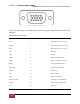
3. Rear Port Specification and Connection Examples
Page 29
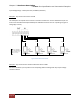
Figure 15 PTZ and Keyboard in RS-485
Alarm Out
Connecting the alarm out:
Each alarm output can be controlled/switched by DVR unit and its application software. Each device
must be wired to C (Common) and NO (Normally Open). It passes no voltage (dry contact)
Figure 16 Alarm Out
Sensor Input
Connecting the Inputs:
Each alarm input can be controlled/switched by a device such as a motion/IR sensor, door contact
sensor, and similar devices. Each device can either be wired as N/O or N/C (Normally Open/Normally
Closed).
Specifications:
Alarm Input: +5v