
DVR User Manual


Chapter 2. Hardware Description
3. Rear Port Specification and Connection Examples
Page 22
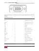
[Please refer to the Figure 1 (4ch Model), Figure 2 (9ch Model), Figure 3 (16ch Model) item marked “③”
VGA Port].
VGA Pin Configuration Table
Signal Type
Pin Number
Description
RED
1
Red video (75 ohm, 0.7 V p-p)
GREEN
2
Green video (75 ohm, 0.7 V p-p)
BLUE
3
Blue video (75 ohm, 0.7 V p-p)
RES
4
Reserved
GND
5
Ground
RGND
6
Red ground (Red return)
GGND
7
Green ground (Green return)
BGND
8
Blue ground (Blue return)
KEY / PWR
SGND
9
10
Key (not used) / +5V DC
Sync ground
ID0
11
Monitor ID bit 0
SDA
12
Bidirectional data line
HSYNC or CSYNC
13
Horizontal or Composite Sync
VSYNC
14
Vertical Sync and data clock
SCL
15
Data clock
Table 6 VGA Pin Configuration
Figure 5. VGA Pin Configuration