
Installation Guide

VA Series Installation Guide V1.1 5
Important
Read this before connecting the amplier to AC mains
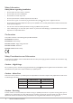
VA Series ampliers are pre-congured at the factory to operate on either a 115 V or a 230 V AC mains supply.
Before applying power to the unit, please check the rear panel to ensure that the version you have is correctly set
for your local supply voltage.
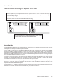
The MAINS VOLTAGE SELECTOR switch on the rear panel will show either 230 V or 115 V, as shown below.
The warning sticker above the switch will conrm the factory setting.
POWER INPUT
230V ±10%
POWER
40-60 Hz
MAX: 241 W
CAUTION:
REPLACE WITH SAME TYPE
T2AH 250V FUSE
ATTENTION:
UTILIZER UN FUSIBLE DE RECHARGE DE
MEME TYPE DE T2AH 250V.
WARNING!
THIS PRODUCT IS FACTORY
CONFIGURED FOR 230V SUPPLY.
BEFORE POWERING, VERIFY THAT
THIS MATCHES THE SUPPLY
VOLTAGE OF THE INSTALLATION.
POWER INPUT
115
115V ±10%
POWER
40-60 Hz
MAX: 241 W
WARNING!
THIS PRODUCT IS FACTORY
CONFIGURED FOR 115V SUPPLY.
BEFORE POWERING, VERIFY THAT
THIS MATCHES THE SUPPLY
VOLTAGE OF THE INSTALLATION.
CAUTION:
REPLACE WITH SAME TYPE
T4AH 250V FUSE
ATTENTION:
UTILIZER UN FUSIBLE DE RECHARGE DE
MEME TYPE DE T4AH 250V.
VA2120
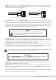
DO NOT CONNECT YOUR VA SERIES AMPLIFIER TO AN AC SUPPLY
WITHOUT FIRST VERIFYING THE VOLTAGE SETTING.
Introduction
The Cloud VA2120 and VA4120 are cost-effective audio power ampliers for use in all types of commercial premises. They have
been designed to be as simple to install and operate as possible.
The two models are identical in terms of facilities, and differ only in the number of channels: two (VA2120) or four (VA4120).
Each channel can deliver 120 W. The ampliers can drive either low-impedance loudspeakers directly (4 ohms minimum) or
25/70/100 V-line loudspeaker distribution systems via the tapped secondary winding of the internally tted line transformer.
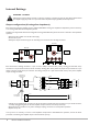
Both models of amplier are shipped ready for connection to 25/70/100 V-line systems. Instructions on converting the outputs
for low-impedance operation can be found on page 8.
The ampliers incorporate a limiter in each channel to protect both the output stage and loudspeakers. This reduces excessive
signal levels to ensure that clipping does not occur. Further protection circuitry disconnects the output if the maximum
permitted internal temperature is exceeded, or if DC is detected at the output terminals.
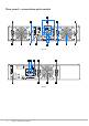
All connections are made on the rear panel, using detachable screw-terminal type connectors (Phoenix-compatible). Each
channel has a preset level control and a switchable high-pass ter to mitigate the effect of transformer saturation at low
frequencies when driving 25/70/100 V-line systems.
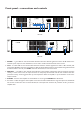
The front panel has a set of LEDs for each channel, conrming signal presence, excessive level and amplier protection activity.
Both models are forced-air cooled by fans mounted on the rear panel; airow is front-to-rear.