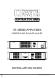
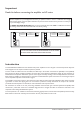
CONTRACTOR SERIES VA SERIES AMPLIFIERS MODELS VA2120 AND VA4120 VA 2120 2 CHANNEL POWER AMPLIFIER POWER 1 2 PROTECT CLIP SIGNAL POWER VA 4120 4 CHANNEL POWER AMPLIFIER POWER 1 2 3 4 PROTECT CLIP SIGNAL POWER INSTALLATION GUIDE VA Series Installation Guide V1.
WARNING: To reduce the risk of fire or electric shock, do not expose this appliance to rain or moisture. CAUTION: Use of controls or adjustments or performance of procedures other than those specified may result in hazardous radiation exposure.
IMPORTANT SAFETY INSTRUCTIONS 1. Read these Instructions. 2. Keep these Instructions. 3. Heed all Warnings. 4. Follow all Instructions. 5. Do not use this apparatus near water. 6. Clean only with a dry cloth. 7. Do not block any ventilation openings. Install in accordance with the manufacturer’s instructions. 8. Do not install near any heat sources such as radiators, heat registers, stoves or other apparatus (including amplifiers) that produce heat. 9.
Safety Information Safety Notes regarding Installation • Do not expose the unit to water or moisture. • Do not expose the unit to naked flames. • Do not block or restrict any air vent. • Do not operate the unit in ambient temperatures above 35°C • Do not touch any part or terminal carrying the hazardous live symbol • Do not perform any internal adjustments unless you are qualified to do so and fully understand the hazards associated with mains-operated equipment.
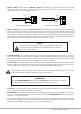
Important Read this before connecting the amplifier to AC mains VA Series amplifiers are pre-configured at the factory to operate on either a 115 V or a 230 V AC mains supply. Before applying power to the unit, please check the rear panel to ensure that the version you have is correctly set for your local supply voltage. The MAINS VOLTAGE SELECTOR switch on the rear panel will show either 230 V or 115 V, as shown below. The warning sticker above the switch will confirm the factory setting.
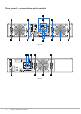
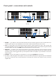
Rear panel – connections and controls 1 4 3 4 7 3 6 2 4 5 3 VA 4120 5 WARNING! THIS PRODUCT IS FACTORY CONFIGURED FOR 230V SUPPLY. BEFORE POWERING, VERIFY THAT THIS MATCHES THE SUPPLY VOLTAGE OF THE INSTALLATION. 2 CAUTION: REPLACE WITH SAME TYPE T4AH 250V FUSE 1 MAX: 241 W POWER 4 OUTPUT 2 OUTPUT 1 40-60 Hz ATTENTION: UTILIZER UN FUSIBLE DE RECHARGE DE MEME TYPE DE T4AH 250V. 230V ±10% INPUT 1 65Hz HPF 4 LEVEL C.V. OUTPUTS C.V.
1. INPUT 1, INPUT 2 (both models) and INPUT 3, INPUT 4 (VA4120 only) – balanced line inputs for each amplifier channel, using 3-pin, 3.5 mm-pitch screw-terminal connectors. Mating connectors are supplied. Connect balanced or unbalanced sources according to the diagrams below: ‘cold’ (-) ‘hot’ (+) signal 3 3 2 2 screen 1 1 screen Connecting an unbalanced source Connecting a balanced source 2.
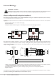
Internal Settings WARNING – DANGER Changing the internal settings requires to open the unit. Prior to opening the unit, the unit shall be disconnected from any AC supply. Any work on an open unit shall be expedited only by qualified, certified personnel. Output configuration (hi-voltage/low-impedance) Each channel of a VA Series amplifier may be configured EITHER for driving low impedance loudspeakers (4 ohms minimum),. or for driving 25/70/100 V-line loudspeaker systems.
Front panel – connections and controls VA 4120 4 CHANNEL POWER AMPLIFIER POWER 1 2 3 4 PROTECT CLIP SIGNAL POWER 5 1 2 3 4 5 VA 4120 VA 2120 2 CHANNEL POWER AMPLIFIER POWER 1 2 PROTECT CLIP SIGNAL POWER 5 3 2 1 4 VA 2120 1. SIGNAL – a green LED for each channel which illuminates when the channel’s signal level is above -45 dB relative to the maximum power output. In most installations, it can be used to confirm that the channel’s source is active. 2.
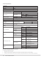
Technical Specifications Line Inputs Frequency Response Input impedance Headroom Noise Speaker Output Output Power (1 kHz continuous sine wave) Minimum load Frequency response THD + N Protection General Power input Fuse details Normal operating temperature Cooling Power Consumption Heat Loss Dimensions (W x H x D) 20 Hz to 20 kHz, ±1 dB 47 kohms 16 dB <-85 dB (22 kHz bandwidth) VA2120 VA4120 Low-Z output High-Z output 2 x 120 watts 4 x 120 watts 4 ohms 25 V-line 5.
VA Series Installation Guide V1.
www.cloud.co.uk www.cloudusa.pro CONTRACTOR SERIES VA Series Installation Guide V1.