
User manual

VB7009
VB7009VB7009
VB7009
User Manual
User ManualUser Manual
User Manual
38
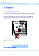
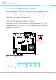
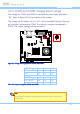
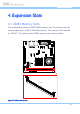
3.2.2. COM3 and COM4 Voltage Select Jumper
The voltage for COM3 and COM4 is controlled by the jumper labeled as
“J13”. Refer to Figure 32 for the location of the jumper.
The voltage can be either +5V or +12V. +5V is the default setting. The even
pin numbers correspond to COM3. The odd pin numbers correspond to
COM4. The jumper settings are shown below.
5
2
1
6
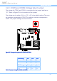
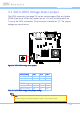
Figure
Figure Figure
Figure 32
3232
32: Voltage select jumpers for COM3 and COM4
: Voltage select jumpers for COM3 and COM4: Voltage select jumpers for COM3 and COM4
: Voltage select jumpers for COM3 and COM4
COM
COMCOM
COM4
44
4 Setting
Setting Setting
Setting
Pin 1
Pin 1Pin 1
Pin 1
Pin 3
Pin 3Pin 3
Pin 3
Pin 5
Pin 5Pin 5
Pin 5
+5V (default) On On Off
+12V Off On On
COM
COMCOM
COM3
33
3 Setting
Setting Setting
Setting
Pin 2
Pin 2Pin 2
Pin 2
Pin 4
Pin 4Pin 4
Pin 4
Pin 6
Pin 6Pin 6
Pin 6
+5V (default) On On Off
+12V Off On On
Table
Table Table
Table 28
2828
28: Jumper settings for COM3 and COM4
: Jumper settings for COM3 and COM4: Jumper settings for COM3 and COM4
: Jumper settings for COM3 and COM4