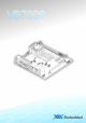
USER MANUAL VB7009 Mini-ITX embedded board 1.
Copyright Copyright © 2013 VIA Technologies Incorporated. All rights reserved. No part of this document may be reproduced, transmitted, transcribed, stored in a retrieval system, or translated into any language, in any form or by any means, electronic, mechanical, magnetic, optical, chemical, manual or otherwise without the prior written permission of VIA Technologies, Incorporated. Trademarks All trademarks are the property of their respective holders.
Battery Recycling and Disposal Only use the appropriate battery specified for this product. Do not re-use, recharge, or reheat an old battery. Do not attempt to force open the battery. Do not discard used batteries with regular trash. Discard used batteries according to local regulations. Safety Precautions Always read the safety instructions carefully. Keep this User's Manual for future reference. All cautions and warnings on the equipment should be noted.
VB7009 User Manual Box Contents and Ordering Information VB7009VB7009-16 1 x VB7009 embedded board (with C7®-D 1.6 GHz NanoBGA2 processor) 1 x I/O bracket 1 x SATA cable VB7009VB7009-10E 1 x VB7009 embedded board (with C7® 1.0 GHz NanoBGA2 processor) 1 x I/O bracket 1 x SATA cable VB7009VB7009-12XC 1 x VB7009 embedded board (with NanoX2 1.
VB7009 User Manual Table of Contents 1. Product Overview ................................................................ ................................................................................................ ................................................................ 1 1.1. Key Features and Benefits........................................................................... 1 1.1.1. VIA C7®-D / C7® / Nano X2 NanoBGA2 Processor ........................ 1 1.1.2. VIA VX900 Chipset.............
VB7009 User Manual 2.2.11. 2.2.12. 2.2.13. 2.2.14. 2.2.15. 2.2.16. 2.2.17. LVDS Connector.................................................................................... 27 Inverter Connector................................................................................ 29 SPDIF Connector ................................................................................... 30 SPI Pin Header ....................................................................................... 31 LPC Pin Header .......
VB7009 User Manual 6.3. Navigating the BIOS Menus ..................................................................... 54 6.4. Getting Help................................................................................................ 54 6.5. Main Menu ................................................................................................... 55 6.5.1. Standard CMOS Features .................................................................... 55 6.5.2. Advanced BIOS Features......................
VB7009 User Manual 6.10. Hard Disk Boot Priority.............................................................................. 63 6.11. Advanced Chipset Features ..................................................................... 64 6.11.1. LCD Clock Source Control ................................................................. 64 6.11.2. LCD Backlight Control ......................................................................... 64 6.12. PCIE Bus Control ............................................
VB7009 User Manual 6.17.5. NB HD Audio Codec 1........................................................................ 72 6.18. SuperIO Device .......................................................................................... 73 6.18.1. Onboard Serial Ports 1 ~ 4 ................................................................ 73 6.18.2. Onboard Parallel Port ......................................................................... 73 6.18.3. Parallel Port Mode......................................
VB7009 User Manual 6.22.1. Init Display First ..................................................................................... 82 6.22.2. Resources Controlled By..................................................................... 82 6.23 PC Health Status ................................................................................................ 83 6.24 Frequency/Voltage Control ..................................................................... 84 6.24.1 DRAM Clock.............................
VB7009 User Manual A.2.7. Network Access – Gigabit Ethernet File Transmitting .................................................................................................................................... 99 A.2.8. Network Access – Gigabit Ethernet File Transmitting. 99 A.3. VB7009-12XC ....................................................................................................100 A.3.1. System Idle – Windows 7 32-bit ...................................................
VB7009 User Manual Lists of Figures Figure 1: Layout diagram of the VB7009 mainboard (top view) ............................ 6 Figure 2: Mounting holes and dimensions of the VB7009 mainboard .................. 7 Figure 3: External I/O port dimensions of the VB7009 mainboard........................ 7 Figure 4: Height distribution of the VB7009 mainboard........................................... 8 Figure 5: External I/O ports...................................................................................
VB7009 User Manual Figure 32: Voltage select jumpers for COM3 and COM4 ..................................... 38 Figure 33: Voltage select jumpers for COM5 and COM6 ..................................... 39 Figure 34: SATA DOM voltage select jumper.......................................................... 40 Figure 35: LVDS power select jumper........................................................................ 41 Figure 36: Backlight power select jumper....................................................
VB7009 User Manual Lists of Tables Table 1: PS/2 port pinout .............................................................................................. 10 Table 2: VGA port pinout ............................................................................................. 11 Table 3: COM port pinout ............................................................................................ 12 Table 4: Parallel port pinout ...............................................................................
VB7009 User Manual Table 32: Backlight power select jumper settings .................................................. 42 Table 33: VB7009 mating connector vendor lists .................................................
VB7009 User Manual 1. Product Overview The VIA VB7009 Mini-ITX mainboard is an entry-level native x86 mainboard designed mainly for embedded and thin client applications. It can also be used for various domain applications such as desktop PC, industrial PC, etc. The mainboard is based on the VIA VX900 Unified Digital Media IGP chipset that features the VIA Chrome™ 9 HC with 2D/3D graphics and video accelerators for rich digital media performance.
VB7009 User Manual The VIA Nano X2 is a 64-bit dual core processor that can deliver an improved multitasking ability without consuming more power. It is based on the latest 40 nanometer process technology. 1.1.2. VIA VX900 Chipset The VIA VX900 Unified Digital Media Chipset is designed to enable high quality digital video streaming and DVD playback in a new generation of fanless, small form factor PCs and IA devices.
VB7009 User Manual 1.2. Product Specifications Processor ® 1 VIA C7 -D 1.6 GHz NanoBGA2 (for VB7009-16 SKU ) Supports 800MHz Front Side Bus 21 x 21 mm FCBGA ® 2 VIA C7 1.0 GHz NanoBGA2 (for VB7009-10E SKU ) Supports 400MHz Front Side Bus 21 x 21 mm FCBGA 1 VIA Nano X2 1.
VB7009 User Manual Onboard I/O Connectors 2 x USB 2.0 pin headers for 4 USB ports 2 x SATA 2.
VB7009 User Manual BIOS Award BIOS 8 Mbit SPI flash memory Supported Operating System Windows 7 Windows Embedded Standard 7 Windows Embedded POSReady 7 Windows Embedded Standard Windows XP Windows CE Linux System Monitoring Monitoring & Management Wake-on-LAN Wake-on-Keyboard Wake-on-Mouse RTC Timer to Power On AC power failure recovery Operating Conditions Operating Temperature 0°C up to 60°C Operating Humidity 0% ~ 95% (relative humidity; non-condensing)
VB7009 User Manual 1.3. Layout Diagram Figure 1: Layout diagram of the VB7009 mainboard (top view) view) Notes: The additional COM pin headers labeled as “COM5” and “COM6” are available only in VB7009-12XC SKU.
VB7009 User Manual 1.4. Product Dimensions 170.00 mm 7.92 mm 10.16 mm 33.02 mm 39.37 mm 170.00 mm 4.97 mm 6.17 mm 6.35 mm Figure 2: Mounting holes and dimensions of the VB7009 mainboard 31.50 mm 25.55 mm 21.75 mm 19.00 mm 6.25 mm 6.50 mm 6.50 mm 143.61 mm 121.86 mm 100.21 mm 73.99 mm 55.99 mm 37.98 mm 0.00 11.90 mm 0.
VB7009 User Manual 1.5. Height Distribution Height: 38.50 mm Height: 32.00 mm Height: 33.00 mm Height: 35.00 mm Height: 34.
VB7009 User Manual 2. I/O Interface The VIA VB7009 has a wide selection of interfaces integrated into the board. It includes a selection of frequently used ports as part of the external I/O coastline. 2.1. External I/O Ports PS2 Mouse port Parallel port RJ-45 ports (GigaLAN) Line-In Line-Out MIC-In VGA port COM port USB 2.
VB7009 User Manual 2.1.1. PS/2 Port The mainboard has two integrated PS/2 ports for keyboard and mouse. Each port is using the 6-pin Mini-DIN connector. The color purple is use for a PS/2 keyboard while the color green is use for a PS/2 mouse. The pinout of the PS/2 port are shown below. Pin Signal 1 Data 2 NC 3 GND 4 +5V 5 Clock 6 NC 5 6 4 3 2 1 Table 1: PS/2 port pinout Figure 6: PS/2 port pinout diagram 2.1.2. VGA Port The integrated 15-pin VGA port uses a female DE-15 connector.
VB7009 User Manual 4 NC 12 VGA-SPD 5 GND 13 VGA_HS 6 GND 14 VGA_VS 7 GND 15 VGA-SPCLK 8 GND Table 2: VGA port port pinout 11
VB7009 User Manual 2.1.3. COM Port The integrated 9-pin COM port uses a male DE-9 connector. The COM (COM1) port supports the RS-232 standard. The pinout of the COM port is shown below.
VB7009 User Manual 2.1.4. Parallel Port The integrated 25-pin parallel port uses a female DB-25 connector. A parallel port is a standard printer port that supports Enhanced Parallel Port (EPP) and Extended Capabilities Parallel Port (ECP) modes. The pinout of the Parallel port is shown below.
VB7009 User Manual 2.1.5. RJ45 LAN port: Gigabit Ethernet The two integrated 8-pin Gigabit Ethernet ports are using an 8 Position 8 Contact (8P8C) receptacle connector (commonly referred to as RJ45). The Gigabit Ethernet ports are controlled by VIA Gigabit Ethernet controller. The pinout of the Gigabit Ethernet port is shown below.
VB7009 User Manual 2.1.6. USB 2.0 Port There are four integrated USB 2.0 ports located below the two RJ45 LAN port at the external I/O panel. The USB 2.0 interface port gives complete Plug and Play and hot swap capability for external devices and it complies with USB UHCI, rev. 2.0. Each USB port is using the USB Type A receptacle connector. The pinout of the typical USB port is shown below. Pin Signal 1 +5VSUS 2 Data- 3 Data+ 4 GND Table 7: USB 2.
VB7009 User Manual 2.1.7. Audio Ports There are three audio jack receptacles integrated into a single stack on the I/O coastline. Each receptacle can fit a 3.5 mm Tip Ring Sleeve (TRS) connector to enable connections to Line-Out Line-In, and MIC-in. The Line-Out jack is for connecting to external speakers or headphones. The Line-In jack is for connecting an external audio devices such as CD player, tape player and etc.. The MIC-In jack is for connecting to a microphone.
VB7009 User Manual 2.2. Onboard Connectors 2.2.1. ATX Power Connector The mainboard has a 20-pin ATX power connector onboard. The ATX power connector is labeled as “ATX_POWER1”. The pinout of the ATX power connector is shown below. 20 10 11 1 Figure 13: 13: ATX power connector Pin Signal Pin Signal 1 +3.3V 11 +3.3V 2 +3.
VB7009 User Manual 2.2.2. CMOS Battery Slot The mainboard is equipped with a CMOS battery slot, which is compatible with CR2032 coin batteries. The CMOS battery slot is labeled as “BAT2”. When inserting a CR2032 coin battery, be sure that the positive side is facing the locking clip.
VB7009 User Manual 2.2.3. Front Panel Pin Header The front panel pin header consists of 15 pins in a 16-pin block. Pin 15 is keyed. The front panel pin header is labeled as “F_PANEL1”. It provides access to system LEDs, power, reset, system speaker and HDD LED. The pinout of the front panel pin header is shown below.
VB7009 User Manual 2.2.4. Front Audio Pin Header In addition to the TRS audio jacks on the external I/O coastline, the mainboard has a pin header for Line-Out and MIC-In. The pin header is labeled as “F_AUDIO1”. The pinout of the pin header is shown below.
VB7009 User Manual 2.2.5. SMBus Pin Header The SMBus pin header consists of three pins that allow connecting the SMBus devices. Devices communicate with a SMBus host and/or other SMBus devices using the SMBus interface. It is labeled as “SMBUS1”. The pinout of the SMBus pin header is shown below.
VB7009 User Manual 2.2.6. CPU and System Fan Connectors There are two fan connectors on board: one for the CPU and one for the chassis. The fan connector for the CPU is labeled as “CPUFAN1” and the fan connector for the system is labeled as “SYSFAN1”. The fans provide variable fan speeds controlled by the BIOS. The pinout of the fan connectors is shown below.
VB7009 User Manual 2.2.7. SATA Connectors The two SATA connectors on board can support up to 3 Gb/s transfer speeds, enabling fast data file transfer with independent DMA operation. The SATA connectors are labeled as “SATA1” and “SATA2”. The pinout of the SATA connectors are as shown below.
VB7009 User Manual 2.2.8. USB 2.0 Pin Headers The mainboard has two USB 2.0 pin headers blocks that support up to four USB 2.0 ports. The pin header blocks are labeled as USB_4, and “USB_5”. The pinout of the USB pin headers are shown below. USB_5 USB_4 1 1 2 2 10 10 Figure 20: 20: USB 2.
VB7009 User Manual 2.2.9. COM Pin Headers There are COM pin headers on the mainboard in addition to the COM port 1 on the external I/O. Each COM pin header supports the RS-232 standard. The COM pin headers labeled as “COM2, COM3 and COM4” are available in VB7009-16 and VB7009-10E SKUs, while the additional “COM5” and “COM6” pin headers are offered only in VB7009-12XC SKU. All of the COM pin headers can support +5V or +12V. See page 37 for details on setting the voltage.
VB7009 User Manual 2.2.10. PS/2 Keyboard and Mouse Pin Header The mainboard has a pin header for a PS/2 keyboard and mouse. The pin header is labeled as “JKB/MS1”. The pinout of the pin header is shown below.
VB7009 User Manual 2.2.11. LVDS Connector The mainboard has one 40-pin LVDS connector on the bottom side. The LVDS connector is labeled as “PANEL_CONN1”. The pinout of the connector is shown below.
VB7009 User Manual 33 NC 34 -A3_L 35 NC 36 A3_L 37 NC 38 SPCLK1 39 NC 40 SPD1 Table 19: 19: LVDS connector pinout 28
VB7009 User Manual 2.2.12. Inverter Connector The mainboard has one Inverter connector on the bottom side. The Inverter connector is labeled as “INVERTER1”. The pinout of the connector is shown below.
VB7009 User Manual 2.2.13. SPDIF Connector The mainboard has one 3-pin SPDIF (Sony Philips Digital Interface) connector. The SPDIF output provides digital audio to external speakers or compressed AC3 data to an external Dolby Digital Decoder. The connector is labeled as “SPDIF”. The pinout of the connector is shown below.
VB7009 User Manual 2.2.14. SPI Pin Header The mainboard has one 8-pin SPI pin header. The SPI (Serial Peripheral Interface) pin-header is used to connect to the SPI BIOS programming fixture. The pin header is labeled as “SPI1”. The pinout of the pin header is shown below.
VB7009 User Manual 2.2.15. LPC Pin Header The mainboard has one LPC pin header for connecting LPC devices. The pin header is labeled as “LPC1”. The pinout of the pin header is shown below. 2 1 19 Figure 27: 27: LPC pin header Pin Signal Pin Signal 1 LPCAD1 2 LPC33CLK 3 -LPCRST 4 GND 5 LPCAD0 6 LPC48CLK 7 LPCAD2 8 -LPCFRAME 9 SERIRQ 10 LPCAD3 11 -LPCDRQ1 12 -EXTSMI 13 +5V 14 +3.3V 15 +5V 16 +3.
VB7009 User Manual 2.2.16. Digital I/O Pin Header The onboard Digital I/O pin header supports up to four GPO and four GPI signals. The pin header is labeled as “DIO1”. The pinout of the pin headers are shown below.
VB7009 User Manual 2.2.17. Temperature Sensor Pin Header The mainboard supports a pin header (3-pin) that allows the connection of a temperature sensor cable for detecting the system’s internal air temperature. The temperature reading can be seen in the BIOS Setup Utility. The pin header is labeled as “J5”. The pin out of the temperature sensor pin header is shown below.
VB7009 User Manual 3. Jumpers 3.1. Clear CMOS Jumper The onboard CMOS RAM stores system configuration data and has an onboard battery power supply. To reset the CMOS settings, set the jumper on pins 2 and 3 while the system is off. Return the jumper to pins 1 and 2 afterwards. Setting the jumper while the system is on will damage the mainboard. The default setting is on pins 1 and 2.
VB7009 User Manual Note: Except when clearing the RTC RAM, never remove the cap from the CLEAR_CMOS jumper default position. Removing the cap will cause system boot failure. Avoid clearing the CMOS while the system is on; it will damage the mainboard.
VB7009 User Manual 3.2. COM Voltage Select Jumpers Each of the additional COM ports (available through the onboard COM pin headers, see page 25) can support both +5V and +12V. COM2 has its own pin header block. COM3 and COM4 share a single pin header block. COM5 and COM6 also share a single pin header block. 3.2.1. COM2 Voltage Select Jumper The voltage for COM2 is controlled by the jumper labeled as “J12”. The voltage can be either +5V or +12V. +5V is the default setting.
VB7009 User Manual 3.2.2. COM3 and COM4 Voltage Select Jumper The voltage for COM3 and COM4 is controlled by the jumper labeled as “J13”. Refer to Figure 32 for the location of the jumper. The voltage can be either +5V or +12V. +5V is the default setting. The even pin numbers correspond to COM3. The odd pin numbers correspond to COM4. The jumper settings are shown below.
VB7009 User Manual 3.2.3. COM5 and COM6 Voltage Select Jumper The voltage for COM5 and COM6 is controlled by the jumper labeled as “J14”. Refer to Figure 33 for the location of the jumper. The voltage can be either +5V or +12V. +5V is the default setting. The even pin numbers correspond to COM5. The odd pin numbers correspond to COM6. The jumper settings are shown below.
VB7009 User Manual 3.3. SATA DOM Voltage Select Jumper The SATA connectors (see page 23) can be used to support Disk-on-Module (DOM) flash drives. When the jumpers are set, +5V will be delivered to the 7th pin of the SATA connectors. The pin jumper is labeled as “J2”. The jumper settings are shown below.
VB7009 User Manual 3.4. Panel Power Select Jumper The mainboard has a jumper that controls the voltage delivered to the LVDS panel connector. The jumper is labeled as “PVDD1”. The jumper settings are shown below. 1 Figure 35: 35: LVDS power select jumper Panel Voltage Pin 1 Pin 2 +5V On On Pin 3 Off +3.
VB7009 User Manual 3.5. Backlight Power Select Jumper The mainboard has a jumper that controls the input voltage delivered to the LVDS inverter connector. The jumper is labeled as “IVDD_SEL1”. The jumper settings are shown below.
VB7009 User Manual 4. Expansion Slots 4.1. DDR3 Memory Slots The mainboard provide one DDR3 DIMM memory slot. The memory slot can accommodate up to 4 GB of 1066 MHz memory. The memory slot is labeled as “DIMM1”. The location of the DDR3 memory slot is shown below.
VB7009 User Manual 4.1.1. Installing a Memory Module Step 1 Disengage the locking mechanism at both ends of the DIMM slot by pressing the retaining clips outward. Figure 38: 38: Unlocking the memory DIMM slot Step 2 Align the notch on the DIMM memory module with the counter part on the DIMM slot.
VB7009 User Manual Step 3 Insert the DIMM memory module into the slot and push down at both ends until the locking clips lock the DIMM memory module into place.
VB7009 User Manual 4.1.2. Removing a Memory Module Step 1 To disengage the locking clips, push outward the locking clips on both ends of memory slot. When the locking clips have cleared, the DIMM memory module will automatically pop up. Remove the memory module.
VB7009 User Manual 4.1.3. PCI Slot The onboard PCI slot, labeled as “PCI_SLOT1”, supports 5V 32-bit PCI cards. It is not compatible with PCI cards requiring 3.3V signaling. The location of the PCI slot is shown below. key notch Figure 42: 42: PCI slot Note: 1. The orientation of PCI card can be changed from vertical to horizontal using a riser card module. 2. When adding or removing expansion card, unplug first the power supply.
VB7009 User Manual 5. Hardware Installation 5.1. Installing into a Chassis The VB7009 can be fitted into any chassis that has the mounting holes for compatible with the standard Mini-ITX mounting hole locations. Additionally, the chassis must meet the minimum height requirements for specified areas of the mainboard. If a riser card module is being used, the chassis will need to accommodate the additional space requirements. 5.1.1.
VB7009 User Manual coastline should have a buffer of at least 5.00 mm. The two sides adjacent to the I/O coastline should have at least a 10.00 mm buffer. For the side that is close to the PCI slot, the buffer should be at least 100.00 mm if a riser card module will be used. 5.1.2. Suggested minimum chassis height The figure below shows the suggested minimum height requirements for the internal space of the chassis. It is not necessary for the internal ceiling to be evenly flat.
VB7009 User Manual 5.1.3. Suggested keepout areas The figure below shows the areas of the mainboard that is highly suggested to leave unobstructed.
VB7009 User Manual 52
VB7009 User Manual 6. BIOS Setup Utility 6.1. Entering the BIOS Setup Utility Power on the computer and press Delete during the beginning of the boot sequence to enter the BIOS Setup Utility. If the entry point has passed, restart the system and try again. 6.2.
VB7009 User Manual 6.3. Navigating the BIOS Menus The main menu displays all the BIOS setup categories. Use the / Left Right and / Up Down arrow keys to select any item or sub-menu. Descriptions of the selected/highlighted category are displayed at the bottom of the screen. The small triangular arrowhead symbol next to a field indicates that a submenu is available (see figure below). Press Enter to display the sub-menu.
VB7009 User Manual 6.5. Main Menu The Main Menu contains thirteen setup functions and two exit choices. Use arrow keys to select the items and press Enter to accept or enter Sub-menu.
VB7009 User Manual 6.5.5. Power Management Setup Use this menu to set onboard power management functions. 6.5.6. PnP/PCI Configurations Use this menu to set the PnP and PCI configurations. 6.5.7. PC Health Status This menu shows the PC health status. 6.5.8. Frequency/Voltage Control Use this menu to set the system frequency and voltage control. 6.5.9. Load Optimized Defaults Use this menu option to load BIOS default settings for optimal and high performance system operations. 6.5.10.
VB7009 User Manual 6.6.
VB7009 User Manual 6.7. IDE Channels Channel 0 Master Phoenix - AwardBIOS CMOS Setup Utility IDE Channel 0 Master IDE HDD Auto-Detection [Press Enter] IDE Channel 0 Master Access Mode [Auto] [Auto] Item Help Menu Level Capacity 0 MB Cylinder Head Precomp Landing Zone Sector 0 0 0 0 0 : Move Enter: Select +/-/PU/PD: Value F5: Previous Values To auto-detect the HDD's size, head...
VB7009 User Manual The specifications of your drive must match with the drive table. The hard disk will not work properly if you enter incorrect information in this category. Select “Auto” whenever possible. If you select “Manual” “Manual”, make sure the information is from your hard disk vendor or system manufacturer. Below is a table that details required hard drive information when using the “Manual” mode. Settings Description [storage] Channel The name of this match the name of the menu.
VB7009 User Manual 6.8.
VB7009 User Manual VIA Networking Boot from network drive Disabled Disable the boot device sequence 6.8.3. Boot Other Device Enables the system to boot from alternate devices if the system fails to boot from the “First/Second/Third Boot Device” lists. Settings Description Disabled No alternate boot device allowed Enabled Enable alternate boot device 6.8.4. Boot Up NumLock Status Set the NumLock status when the system is powered on.
VB7009 User Manual 6.9. CPU Feature Phoenix - AwardBIOS CMOS Setup Utility CPU Features Thermal Management PMON support [Thermal Monitor 3] [Disabled] Item Help Menu Level Thermal Monitor 3 Dynamic Ratio & VID transition : Move Enter: Select +/-/PU/PD: Value F5: Previous Values F10: Save ESC: Exit F1: General Help F7: Optimized Defaults 6.9.1. Thermal Management This item sets CPU’s thermal control rule to protect CPU from overheating.
VB7009 User Manual 6.10. Hard Disk Boot Priority Phoenix - AwardBIOS CMOS Setup Utility Hard Disk Boot Priority Item Help 1. Bootable Add-in Cards Menu Level Use < > or < > to select a device, then press < + > to move it up, or < - > to move it down the list. Press to exit this menu.
VB7009 User Manual 6.11.
VB7009 User Manual 6.12. PCIE Bus Control Phoenix - AwardBIOS CMOS Setup Utility PCIE Bus Control PCIE Root Port PCIE Target Link Speed PCIE PE0 Control PCIE Hot-Reset Enable PCIE Root-Port-Reset Enable Maximum Payload Size PCIE ASPM Function : Move 6.12.1. [Enable] [Auto] [Enable] [Disabled] [Disabled] [Auto] [Auto] Enter: Select +/-/PU/PD: Value F5: Previous Values Item Help Menu Level F10: Save ESC: Exit F1: General Help F7: Optimized Defaults PCIE Root Port Settings: [Disabled, Enabled] 6.12.
VB7009 User Manual 6.12.7.
VB7009 User Manual 6.13. UMA & P2P Bridge Control Phoenix - AwardBIOS CMOS Setup Utility UMA & P2P Bridge Control UMA Enable VGA Share Memory Size CPU Direct Access FB Select Display Device Select Display Device 1 Select Display Device 2 Panel Type Engine Clock Control x ECLK Frequency in MHz : Move 6.13.1.
VB7009 User Manual 6.13.6. Select Display Device 2 This setting refers to the type of display device 2 being used with the system. Settings: [CRT, LCD] 6.13.7. Panel Type Key in a HEX number. Settings: [Min = 0000, Max = 0000F] 6.13.8.
VB7009 User Manual 6.14. CPU & PCI Bus Control Phoenix - AwardBIOS CMOS Setup Utility CPU & PCI Bus Control PCI Master 0 WS Write PCI Delay Transaction SB P2P Bridge : Move 6.14.1. Item Help [Enabled] [Enabled] [Disabled] Enter: Select +/-/PU/PD: Value F5: Previous Values Menu Level F10: Save ESC: Exit F1: General Help F7: Optimized Defaults PCI Master 0 WS Write Settings: [Enabled, Disabled] 6.14.2. PCI Delay Transaction Settings: [Disabled, Enabled] 6.14.3.
VB7009 User Manual 6.15.
VB7009 User Manual 6.16. VIA OnChip IDE Device Phoenix - AwardBIOS CMOS Setup Utility VIA OnChip IDE Device OnChip SATA [Enabled] Item Help Menu Level : Move 6.16.1.
VB7009 User Manual 6.17. VIA OnChip PCI Device Phoenix - AwardBIOS CMOS Setup Utility VIA OnChip PCI Device Onboard PCIE LAN Hide D1F1 OnChip HDAC Device Clear HDA Wake Enable bit NB HD Audio Codec 1 : Move 6.17.1. Item Help [Enabled] [Disabled] [Enabled] [Enabled] [Enabled] Enter: Select +/-/PU/PD: Value F5: Previous Values Menu Level F10: Save ESC: Exit F1: General Help F7: Optimized Defaults Onboard PCIE LAN Settings: [Enabled, Disabled] 6.17.2. Hide D1F1 Settings: [Enabled, Disabled] 6.
VB7009 User Manual 6.18. SuperIO Device Phoenix - AwardBIOS CMOS Setup Utility SuperIO Device Onboard Serial Port 1 Onboard Serial Port 2 Onboard Serial Port 3 Onboard Serial Port 4 Onboard Parallel Port Parallel Port Mode x ECP Mode Use DMA : Move Enter: Select +/-/PU/PD: Value F5: Previous Values 6.18.1.
VB7009 User Manual ECP mode. Choosing ECP + EPP will allow the onboard parallel port to support both the ECP and EPP modes simultaneously. Settings: [SPP, EPP, ECP, ECP + EPP] 6.18.4. ECP Mode Use DMA ECP (Extended Capabilities Port) has two DMA channels that it can use. The default channel is 3. However, some expansion cards may use channel 3 as well. To solve this conflict, change the ECP channel to 1. Select a DMA channel for the port.
VB7009 User Manual 6.19. USB Device Setting Phoenix - AwardBIOS CMOS Setup Utility USB Device Setting USB USB USB USB USB USB 1.0 Controller 2.0 Controller Operation Mode Keyboard Function Mouse Function Storage Function Item Help [Enabled] [Enabled] [High Speed] [Enabled] [Enabled] [Enabled] Menu Level [Enabled] or [Disabled] Universal Host Controller Interface for Universal Serial Bus *** USB Mass Storage Device Boot Setting *** : Move 6.19.1.
VB7009 User Manual Settings: [Disabled, Enabled] 6.19.5. USB Mouse Function Settings: [Disabled, Enabled] 6.19.6. USB Storage Function Enable or disable legacy support of USB mass storage.
VB7009 User Manual 6.20.
VB7009 User Manual wakeup-capable devices. The system context is saved to main memory, and context is restored from the memory when a "wakeup" event occurs. S1 & S3 Depends on the OS to select S1 or S3. 6.20.3. Soft-Off by PWRBTN Settings Description Delay 4 Sec System is turned off if power button is pressed for more than four seconds. Instant-Off Power button functions as a normal power-on/-off button. 6.20.4. Run VGABIOS if S3 Resume Select whether to run VGA BIOS if resuming from S3 state.
VB7009 User Manual 6.20.9. WDRT Count Key in a DEC number.
VB7009 User Manual 6.21. Wakeup Event Detect Phoenix - AwardBIOS CMOS Setup Utility Wakeup Event Detect PS2KB Wakeup Select PS2KB Wakeup Key Select PS2MS Wakeup Key Select PS2 Keyboard Power ON PS2 Mouse Power ON RTC Alarm Resume x Date (of Month) x Resume Time (hh:mm:ss) : Move 6.21.1.
VB7009 User Manual 6.21.4. PS2 Keyboard Power ON Settings: [Disabled, Enabled] 6.21.5. PS2 Mouse Power ON Settings: [Disabled, Enabled] 6.21.6. RTC Alarm Resume Set a scheduled time and/or date to automatically power on the system. Settings: [Disabled, Enabled] 6.21.7. Date (of Month) This field can only be set if “RTC Alarm Resume” is enabled. The field specifies the date for “RTC Alarm Resume”. 6.21.8. Resume Time (hh:mm:ss) This field can only be set if “RTC Alarm Resume” is enabled.
VB7009 User Manual 6.22. PnP/PCI Configurations Phoenix - AwardBIOS CMOS Setup Utility PnP/PCI Configurations Init Display First Resources Controlled By x IRQ Resources : Move Item Help [PCIEx] Menu Level [Auto(ESCD)] Press Enter Enter: Select +/-/PU/PD: Value F5: Previous Values F10: Save ESC: Exit F1: General Help F7: Optimized Defaults Note: This section covers some very technical items and it is strongly recommended to leave the default settings as is unless you are an experienced user. 6.22.
VB7009 User Manual 6.23 PC Health Status Phoenix - AwardBIOS CMOS Setup Utility PC Health Status VCore +3.3V +5V +12V 1.000V 3.200V 5.100V 11.880V SYSTEM Temp. 30°C CPU FAN System FAN 0 RPM 0 RPM : Move Enter: Select +/-/PU/PD: Value F5: Previous Values Item Help Menu Level F10: Save ESC: Exit F1: General Help F7: Optimized Defaults The PC Health Status displays the current status of all of the monitored hardware devices/components such as CPU voltages, temperatures and fan speeds.
VB7009 User Manual 6.24 Frequency/Voltage Control Phoenix - AwardBIOS CMOS Setup Utility Frequency/Voltage Control Current FSB Frequency Current DRAM Frequency DRAM Clock Spread Spectrum : Move 6.24.1 100 MHz 533 MHz [By SPD] [+/-0.1%] Enter: Select +/-/PU/PD: Value F5: Previous Values Item Help Menu Level F10: Save ESC: Exit F1: General Help F7: Optimized Defaults DRAM Clock This chipset supports synchronous and asynchronous mode between host clock and DRAM clock frequency.
VB7009 User Manual 6.
VB7009 User Manual 6.
VB7009 User Manual Additionally, when a password is enabled, the BIOS can be set to request the password each time the system is booted. This would prevent unauthorized use of the system. See “Security Option” in the “Advanced BIOS Features” section for more details.
VB7009 User Manual 6.
VB7009 User Manual 6.
VB7009 User Manual 7 Driver Installation 7.1 Microsoft Driver Support The VIA VB7009 mainboard is compatible with Microsoft operating systems. The latest Windows drivers can be downloaded from the VIA Embedded website at www.viaembedded.com. For embedded operating systems, the related drivers can be found in the VIA Embedded website at www.viaembedded.com. 7.2 Linux Driver Support The VIA VB7009 mainboard is highly compatible with many Linux distributions.
VB7009 User Manual Appendix A. Power Consumption Report Power consumption tests were performed on the VIA VB7009. The following tables represent the breakdown of the voltage, amp and wattage values while running common system applications. A.1. VB7009-16 The tests were performed based on the following additional components: CPU: CPU: VIA C7®-D 1.
VB7009 User Manual A.1.2. S3 Status – Windows 7 Sleep Power Plane Volts Amperes Watts +3.3V -0.019 0.000 0.000 +5V -0.010 0.011 0.000 +5VSB 5.080 0.370 1.880 +12V -0.020 0.009 0.000 Total Power Consumption 1.880 A.1.3. MP3 Playback – Windows Media Player10 Power Plane Volts Amperes Watts Watts +3.3V 3.192 0.680 2.171 +5V 4.917 2.240 11.014 +5VSB 5.104 0.057 0.291 +12V 11.998 0.086 1.032 Total Power Consumption 14.508 A.1.4. DVD Playback – PowerDVD 8.
VB7009 User Manual +5VSB 4.786 0.227 1.086 +12V 11.884 0.065 0.772 Total Power Consumption 26.475 A.1.6. Functional Test – Run Passmark BurnIn test 6.0 Power Plane Volts Amperes Watts +3.3V 2.797 0.630 1.762 +5V 4.390 6.450 28.316 +5VSB 4.620 0.361 1.668 +12V 11.762 0.074 0.870 Total Power Consumption 32.616 A.1.7. Network Access – Gigabit Ethernet File Transmitting Power Plane Plane Volts Amperes Watts +3.3V 2.798 0.640 1.791 +5V 4.420 6.254 27.
VB7009 User Manual A.1.8. Network Access – Gigabit Ethernet File Transmitting Power Plane Volts Amperes Watts +3.3V 2.966 0.730 2.165 +5V 4.489 7.204 32.339 +5VSB 4.710 0.452 2.129 +12V 11.880 0.090 1.069 Total Power Consumption 37.
VB7009 User Manual A.2. VB7009-10E The tests were performed based on the following additional components: CPU: CPU: VIA C7® 1.0 GHz Chipset: Chipset: VX900 Memory: DDR3 DIMM Kingston HyperX 1600 MHz 4GB HDD SATA: SATA: Fujitsu MJA2250BH 250GB DVDDVD-ROM: ROM: Sony CRX890S Power supply: supply: ATX power supply SevenTeam ST-350GL 350W Operating System: System: Windows 7 32-bit A.2.1. System Idle – Windows 7 32-bit Power Plane Volts Amperes Watts +3.3V 3.248 0.700 2.
VB7009 User Manual A.2.3. MP3 Playback – Windows Media Player10 Power Plane Volts Amperes Watts +3.3V 3.233 0.710 2.295 +5V 4.942 1.827 9.029 +5VSB 5.145 0.062 0.319 +12V 12.051 0.031 0.374 Total Power Consumption 12.017 A.2.4. DVD Playback – PowerDVD 8.0 Power Plane Volts Amperes Watts +3.3V 3.186 0.700 2.230 +5V 4.880 2.060 10.053 +5VSB 5.085 0.071 0.361 +12V 12.030 0.040 0.481 Total Power Consumption 13.125 A.2.5.
VB7009 User Manual A.2.6. Functional Test – Run Passmark BurnIn test 6.0 Power Plane Volts Amperes Watts +3.3V 3.221 0.710 2.287 +5V 4.918 2.050 10.082 +5VSB 5.124 0.068 0.348 +12V 12.049 0.033 0.398 Total Power Consumption 13.115 A.2.7. Network Access – Gigabit Ethernet File Transmitting Power Plane Volts Amperes Watts +3.3V 3.083 0.700 2.158 +5V 4.700 3.573 16.793 +5VSB 4.868 0.147 0.716 +12V 11.961 0.045 0.538 Total Power Consumption 20.205 A.2.8.
VB7009 User Manual A.3. VB7009-12XC The tests were performed based on the following additional components: CPU: CPU: VIA NanoX2 1.2 GHz Chipset: Chipset: VX900 Memory: DDR3 DIMM Kingston HyperX 1600 MHz 4GB HDD SATA: SATA: Fujitsu MJA2250BH 250GB DVDDVD-ROM: ROM: Sony CRX890S Power supply: supply: ATX power supply SevenTeam ST-350GL 350W Operating System: System: Windows 7 32-bit A.3.1. System Idle – Windows 7 32-bit Power Plane Volts Amperes Watts +3.3V 3.065 0.656 2.
VB7009 User Manual A.3.3. MP3 Playback – Windows Media Player10 Power Plane Volts Amperes Watts +3.3V 2.998 0.658 1.973 +5V 4.664 2.577 12.019 +5VSB 4.811 0.098 0.471 +12V 11.971 0.075 0.898 Total Power Consumption 15.361 A.3.4. DVD Playback – Windows Media Player10 Power Plane Volts Amperes Amperes Watts +3.3V 2.990 0.653 1.952 +5V 4.673 2.345 10.958 +5VSB 4.846 0.078 0.378 +12V 11.928 0.077 0.918 Total Power Consumption 14.206 A.3.5.
VB7009 User Manual A.3.6. Functional Test – Run Passmark BurnIn test 6.0 Power Plane Volts Amperes Watts +3.3V 2.993 0.567 1.697 +5V 4.599 6.052 27.833 +5VSB 4.715 0.108 0.509 +12V 11.992 0.038 0.456 Total Power Consumption 30.495 A.3.7. Network Access – Gigabit Ethernet File Transmitting Power Plane Volts Amperes Watts +3.3V 2.889 0.591 1.707 +5V 4.526 4.192 18.973 +5VSB 4.666 0.114 0.532 +12V 11.899 0.052 0.619 Total Power Consumption 21.831 A.3.8.
VB7009 User Manual A.3.9. S5 Status – Windows 7 Shut down Power Plane Volts Amperes Watts +3.3V -0.028 -0.019 0.000 +5V -0.020 -0.027 0.000 +5VSB 5.031 0.361 1.816 +12V -0.028 -0.012 0.000 Total Power Consumption 1.
VB7009 User Manual Appendix B. Mating Connector Vendor Lists The following tables listed the mating connector vendor lists of VB7009 mainboard. Connectors Part No. Mating Vendor & P/N Neltron F_Audio 99G30-05126I 2214S-XXG-85 SAMTEC SSW Series 2214R-XXG-85 Neltron F_PANEL FAN Inverter LVDS SAMTEC 99G30-05009I 2214S-XXG-85 SSW Series 2214R-XXG-85 99G30-020035 99G30-020537 99G30-170152 Neltron N/A 2218H-03 N/A ACES MOLEX 85206-0800 51021-**00 ACES HRS 44002-4000 DF13-**DS-1.
Taiwan Headquarters USA Europe 1F, 531 Zhong-Zheng Road Xindian District, New Taipei City 231, Taiwan 940 Mission Court Fremont, CA 94539 USA In den Dauen 6 53117 Bonn Germany TEL: 886.2.2218.5452 FAX: 886.2.2218.5453 Email: embedded@via.com.tw TEL: 1.510.683.3300 FAX: 1.510.687.4654 Email: embedded@viatech.com TEL: 49.228.688565.0 FAX: 49.228.688565.19 Email: embedded@via-tech.de China Japan Korea Tsinghua Science Park Bldg. 7 No.