
User guide
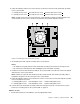
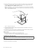


4.Laythecomputeronitssideandremovethefourscrewsattherearofthechassisthatsecurethe
powersupplyassembly.
Figure24.Removingthescrewsforthepowersupplyassembly
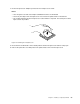
5.Slidethepowersupplyassemblytothefrontofthecomputerandthenliftitoutofthechassis.
6.Makesurethatthenewpowersupplyassemblyisthecorrectreplacement.Somepowersupply
assembliesautomaticallysensethevoltage,somepowersupplyassembliesarevoltagespecic,and
somepowersupplyassemblieshaveavoltage-selectionswitch.Ifyourpowersupplyassemblyhas
avoltage-selectionswitch,makesurethatyousetthevoltage-selectionswitchtomatchthevoltage
availableatyourelectricaloutlet.Ifnecessary,useaballpointpentoslidethevoltage-selectionswitch
tothecorrectposition.
•Ifthevoltagesupplyrangeinyourlocalcountryorregionis100–127Vac,setthevoltage-selection
switchto115V.
•Ifthevoltagesupplyrangeinyourlocalcountryorregionis200–240Vac,setthevoltage-selection
switchto230V.
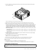
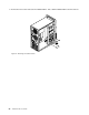
7.Installthenewpowersupplyassemblyintothechassissothatthescrewholesinthepowersupply
assemblyalignwiththoseinthechassis.
8.Installandtightenthefourscrewstosecurethepowersupplyassembly.
Note:UseonlyscrewsprovidedbyLenovo.
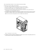
9.Reconnectthepowersupplyassemblycablestothesystemboardandeachofthedrives.
10.Securethepowersupplyassemblycableswiththecableclipsandtiesinthechassis.
Whattodonext:
•Toworkwithanotherpieceofhardware,gototheappropriatesection.
•Tocompletetheinstallationorreplacement,goto“Completingthepartsreplacement”onpage71.
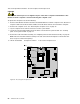
Replacingthemicroprocessor
Attention:
Donotopenyourcomputerorattemptanyrepairbeforereadingandunderstandingthe“Importantsafetyinformation”
onpagev.
Chapter5.Installingorreplacinghardware51