
Replacement Part List


P01-R01-0704
Top Bracket
#1 HingeBottom Bracket
#2, 3, or 4 Hinge
STEP 9 - Installing Door Sections
(Continued)
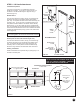
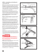
Step 9-6: Place the second section on top of the rst section.
Drive a 3" nail in the jambs at each end and bend it over the
edges of the section to hold the section in place. Attach the
hinges from the top of the rst section to the bottom of the
second. (FIG. 9-D)
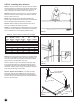
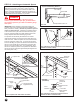
Step 9-7: Place the third section on saw horses. Attach #3
hinges to the ends at the top edge and #1 hinges to each pair
of pre-punched holes along the top edge using #14 x 5/8"
sheet metal screws. (FIG. 9-E)
NOTE: If your door was supplied with more than 1 strut
(consult Table 7-A on bottom of page 10), use 1/4” x 3/4"
self tapping screws to attach strut as shown in FIG. 7-F on
page 10. When pre-drilled holes in strut do not line up vertically
with hinge locations, you will be required to drill (2) 3/16” pilot
holes through the strut, hinge, and back skin of door at each
hinge location, or use a drill or impact wrench with a 7/16”
socket to drive self-tapping screws through strut and hinge and
into door. (FIG. 9-E)
Step 9-8: Place the third section on top of the other sections
and nail in place as before. Attach the hinges from the top of
the previous section to the bottom of this section. (FIG. 9-D)
If you have two sections left, repeat Steps 9-7 and 9-8 using
#4 hinges on the end of the top edge and #1 hinges to all other
stiles along the top edge.
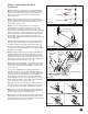
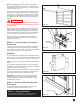
Step 9-9: Place the last section on the saw horses. Attach the
top roller brackets as shown. The top roller brackets are to be
attached with three #14 x 5/8” sheet metal screws. The top of
the bracket goes into the bottom hinge hole.The bottom of the
bracket goes in smaller holes, either 6-1/4” or 8” (depending on
door model) from the top of section. (FIG. 9-F)
NOTE: 8’ and 10’ wide doors with 3” end stiles and windows in
the top section require the addition of (2) 1/4” washers on the
bottom of each top bracket before installation of screws. (See
inset in FIG. 9-F)
If your door was supplied with any struts (consult Table 7-A
on bottom of page 10), use 1/4” x 3/4” self tapping screws to
attach strut as shown in the illustration. When pre-drilled holes
in strut do not line up vertically with hinge hole locations, you
will be required to drill (2) 3/16” pilot holes through the strut
and the back skin of door at each hinge hole location, or use a
drill or impact wrench with a 7/16” socket to drive self-tapping
screws through strut and into door. (FIG. 9-F)
Step 9-10: Place the top section on top of the other sections
and nail in place as before. Attach the hinges from the top of
the previous section to the bottom of this section. (FIG. 9-D)
NOTE: If your door is to be used with an electric operator, you
must reinforce the top section before placing it in the opening.
Proceed to step 10 prior to completing this step.
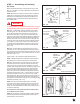
Step 9-11: Place a roller in the top and bottom brackets and
in the tubes in each of the hinges at the ends of each section.
Some hinges have two tubes. Place the roller in the tube that is
farthest from the face of the door. (FIG 9-G)
Safety
Label
FIG. 9-D
#3 Hinge
End Stile
Bottom Edge
#1 Hinge
#14 x 5/8" Sheet
Metal Screws
#14 x 5/8"
Sheet Metal
Screws
1/4" x 3/4"
Self Tapping
Screws
End Stile
Top Bracket
Strut (If Required)
(2) 1/4" Washers
FIG. 9-E
FIG. 9-F
13
FIG. 9-G