
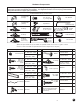
Replacement Part List

P01-R01-0704
STEP 7 - Preparing Bottom Door Section
Step 7-1: Spread the hardware on the garage oor in groups
so that you can easily nd the parts.
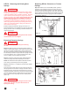
Step 7-2: Find the section with the aluminum weatherstrip
retainer fastened to one edge. The aluminum weatherstrip
retainer is on the bottom edge of the bottom section. Place the
section on saw horses face down. (FIG. 7-A) Be sure to cover
saw horses with carpet or cloth so as not to scratch section.
Step 7-3: Bend and break apart bottom brackets by hand
along end tabs as shown. (FIG. 7-B) Be sure to remove
connecting tab.
Step 7-4: Insert safety tabs on bottom bracket into slots on end
stile of door. Slide bottom bracket up to fully engage tabs. (FIG.
7-C) Attach all hardware with #14 x 5/8” sheet metal screws.
Attach the bottom brackets with two screws to the bottom
corners of the section. Screws go into the end stiles. Hook
the looped ends of the steel lift cable over the buttons on the
bottom brackets. (If your door came with standard extension
springs, the lift cables are the longer and smaller diameter
of the two sets of cable. If your door came with EZ-Set™
Extension Springs, do NOT attach lift cables at this time! Do
NOT use the shorter safety containment cables as lift cables,
as this can cause improper door function). (FIG. 7-D)
Failure to properly engage safety tabs on bottom bracket
into slots on edge of door can result in severe injury when
spring tension is applied.
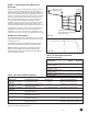
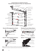
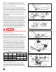
Step 7-5: Hinges are identied by number 1, 2, 3 (and
sometimes 4, on 5 section doors only). This number is
stamped on the hinge. Attach a number 1 hinge to each pair of
pre-punched holes along the top edge of the section using #14
x 5/8” sheet metal screws. The number is stamped on the side
of the hinge that is to be attached to the section. (FIG. 7-E)
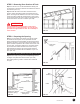
NOTE: Determine if your door thickness is 1-3/8” or 2” and
determine the width of the endstile (FIG. 7-E). If Table 7-
A below shows a need for a reinforcing strut on the bottom
section, it should be attached overlapping the hinges. Use
1/4” x 3/4” self tapping screws to attach strut as shown in
the illustration. When pre-drilled holes in strut do not line up
vertically with hinge locations, you will be required to drill (2)
3/16” pilot holes through the strut, hinge, and door at each
hinge location, or use a drill or impact wrench with a 7/16”
socket to drive self-tapping screws through strut, hinge, and
door. (FIG. 7-F)
NOTE: Doors installed in high windload regions (Florida
and other high wind prone areas) may require additional
reinforcement beyond what is detailed in these instructions.
Please refer to supplemental windload instructions for these
areas.
WARNING
End Stile
Width
Door
Thickness
Bottom
Astragal
#1 Hinge
#14 x 5/8"
Sheet Metal Screws
FIG. 7-C
FIG. 7-B
FIG. 7-A
Table 7- A - Sections Requiring Struts
Aluminum Weatherstrip Retainer
#14 x 5/8" Sheet Metal Screws
Weatherstrip
Safety Tabs
Bottom
Bracket
Bottom Section
10
Slots
Door Door End Stile Section
Thickness Width Width Bttm 3rd* Top
1-3/8"
Up to 14'10"
All - - -
1-3/8" 15'-16' 2-1/2" - - 4
1-3/8" 16'2"-18' 2-1/2" 4 4 4
2" Up to15' - - -
2" 15'2"-20' - - 4
*Section with general safety label.
FIG. 7-D
End Hinge
1/4" x 3/4" Self
Tapping
Screws
End Stile
Strut
FIG. 7-F
FIG. 7-E
One strut per section