CX-A4 Amplifier Installation & User Guide V10.0 Cloud Electronics Limited 140 Staniforth Road, Sheffield, S9 3HF England Tel + 44 (0) 114 244 7051 Fax + 44 (0) 114 242 5462 E-mail info@cloud.co.uk Web site http://www.cloud.co.
CX-A4 INSTALLATION AND OPERATION MANUAL 1 CX-A4 Amplifier Installation and operation manual Contents Section 15-01-09 V10.0 Page 1 Safety Notes...............................................................................2 2 General Description ...................................................................2 3 Installation ..................................................................................2 4 Input Facilities ...................................................................
CX-A4 INSTALLATION AND OPERATION MANUAL 1 2 Safety Notes • • • • • Do not expose the unit to water or moisture Do not expose the unit to naked flames. Do not block or restrict any air vent Do not operate the unit in ambient temperatures above 35oC Do not touch any part or terminal carrying the hazardous live symbol ( ) ) while power is supplied to the unit.
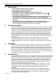
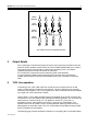
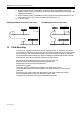
CX-A4 INSTALLATION AND OPERATION MANUAL 3 POWER AMPLIFIER 1 2 3 4 LEVEL CONTROL SOURCE SWITCHES 1 INPUT AMPLFIER 2 1 3 2 1 2 4 3 4 INPUT 1 FROM MONO SOURCE FOUR CHANNELS DRIVEN FROM ONE MONO SOURCE POWER AMPLIFIER 1 2 3 4 LEVEL CONTROL SOURCE SWITCHES 1 INPUT AMPLFIER 2 1 2 INPUT 1 INPUT 2 1 3 2 3 FROM STEREO SOURCE TWO STEREO PAIRS FROM ONE STEREO SOURCE 15-01-09 V10.
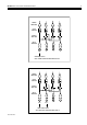
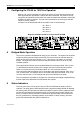
CX-A4 INSTALLATION AND OPERATION MANUAL 4 POWER AMPLIFIER 1 2 3 4 LEVEL CONTROL SOURCE SWITCHES 1 INPUT AMPLFIER 2 1 3 2 4 1 2 3 4 INPUT 1 INPUT 2 INPUT 3 INPUT 4 FOUR CHANNELS OPERATING AS INDEPENDENT AMPLIFIERS 5 Output Details Four 2-pole plug-in screw terminal type connectors (5mm pitch) are provided on the rear panel for the four speaker outputs; these can accommodate flexible leads up to 2.50mm². The plugs for these connectors are provided in the accessory pack.
CX-A4 INSTALLATION AND OPERATION MANUAL 7 5 Configuring the CX-A4 for 100V-line Operation When a CXL-100 is connected to a channel of the CX-A4, that channel must have its 65Hz high-pass filter operational. Without this filter operational, the presence of high input levels at frequencies below 50Hz may result in transformer saturation causing the amplifiers VI limiter to operate. The filter can be switched on by moving the relevant jumper to the ‘IN‘ position.
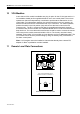
CX-A4 INSTALLATION AND OPERATION MANUAL 10 6 VCA Modules A two-channel VCA module is available as a plug-in option for the CX-A4 (see section 13 for installation details) and is supplied with either one or two control plates. The unit can operate two channels independently or switched to provide stereo attenuation via one control plate. For independent operation, the switch should be in the 'solo' position (in), with the remote level controls connected to both 3 pin connectors.
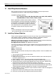
CX-A4 INSTALLATION AND OPERATION MANUAL 12 7 Bose® Equalisation Modules Each channel on the CX-A4 can have Bose® equalisation so that its output will be compensated correctly for a wide range of Bose® speakers. Available Equalisation Modules: - ® Bose Speaker models: M8, M16, M32, MA12, 402, 502A, 502B, 502BEX, 802, MB4, MB24, LT3202, LT4402, LT9402, LT9702 Bose® equalisation modules must be fitted to a stereo EQ card adapter, Cloud part CA340166.
CX-A4 INSTALLATION AND OPERATION MANUAL 8 11. When installing a Bose® equalisation module to a stereo EQ adapter, remove the adapter jumper link for the channel to be equalised and fit the Bose® EQ module to the appropriate connector 12. When installing a Bose® equalisation module, configure the relevant 65Hz filter to ‘IN’ and connect a CXL-100T 100V line transformer (see section 6) 13. Fit the top panel.
CX-A4 INSTALLATION AND OPERATION MANUAL 15 General Specifications Inputs Outputs Balanced via 3 pin XLR type connector. 2 pin plug-in screw terminal type connectors for flexible cables up to 2.5mm² VI limiting, DC offset, Thermal and Switch-on Delay LED indicators on each channel for Signal, Peak & Protect. Force cooled using two speed DC fan. 482.6mm x 88.0mm (2U) x 325.
CX-A4 INSTALLATION AND OPERATION MANUAL 10 CAUTION – Installation Do not expose the unit to water or moisture Do not expose the unit to naked flames. Do not block or restrict any air vent Do not operate the unit in ambient temperatures above 35oC CAUTION – Hazardous Live Do not touch any part or terminal carrying the hazardous live symbol ( ) while power is supplied to the unit as it can result in electric shock.