Tranquility® 27 Split (TTS) Series Indoor Split Geothermal Heat Pump Installation, Operation & Maintenance Instructions 97B0047N02 Revision: 8 May, 2014C Table of Contents Model Nomenclature Safety Storage Pre-Installation Equipment Selection Air Coil Match-ups Air Handler Selection Installation Water Connections Ground-Loop Heat Pump Applications Ground-Water Heat Pump Applications Water Quality Standards Lineset Information Refrigeration Installation Hot Water Generator Electrical - Line Voltage Power C
This page was intentionally left blank.
R e s i d e n t i a l Tr a n q u i l i t y ® 2 7 S p l i t ( T T S ) - 6 0 H z H F C - 4 1 0 A R e v.
R e s i d e n t i a l Tr a n q u i l i t y ® 2 7 S p l i t ( T T S ) - 6 0 H z H F C - 4 1 0 A R e v. : 8 M a y, 2 0 1 4 C Safety Safety Warnings, cautions and notices appear throughout this manual. Read these items carefully before attempting any installation, service, or troubleshooting of the equipment. DANGER: Indicates an immediate hazardous situation, which if not avoided will result in death or serious injury. DANGER labels on unit access panels must be observed.
R e s i d e n t i a l Tr a n q u i l i t y ® 2 7 S p l i t ( T T S ) - 6 0 H z H F C - 4 1 0 A R e v. : 8 M a y, 2 0 1 4 C General Information Storage Pre-Installation Inspection Upon receipt of the equipment, carefully check the shipment against the bill of lading. Make sure all units have been received. Inspect the packaging of each unit, and inspect each unit for damage.
R e s i d e n t i a l Tr a n q u i l i t y ® 2 7 S p l i t ( T T S ) - 6 0 H z H F C - 4 1 0 A R e v. : 8 M a y, 2 0 1 4 C Equipment Selection Air Coil Match-ups Indoor Coil Selection - Tranquility® 27 (TTS) ClimateMaster split system heat pumps are rated in the AHRI directory with a specific indoor coil match. Tranquility 27 Splits are AHRI rated and listed with Tranquility TAH air handlers and TAC cased coils.
R e s i d e n t i a l Tr a n q u i l i t y ® 2 7 S p l i t ( T T S ) - 6 0 H z H F C - 4 1 0 A R e v. : 8 M a y, 2 0 1 4 C Equipment Selection Table 1a: Tranquility® 27 Carrier/Bryant Air Handler Matches for AHRI Performance Compressor Section 026 038 049 064 Air Handler Model FV4 003 005 006 006 A 3 - 14.5 7.42 A 3 - 14.5 7.42 Refrigerant HFC-410A Metering Device Air Coil Type Rows - Fins/in. Face Area (sq. ft.) TXV (required) Slope 3 - 14.5 3.
R e s i d e n t i a l Tr a n q u i l i t y ® 2 7 S p l i t ( T T S ) - 6 0 H z H F C - 4 1 0 A R e v. : 8 M a y, 2 0 1 4 C Equipment Selection Air Handler Selection Air Handler Selection Example Figure 1 shows a typical performance table for a heat pump air handler. Suppose the evaporator temperature required is 50ºF, the capacity required is 35,000 Btuh and the airflow required is 1,200 CFM. Each evaporator temperature listed in the table shows three wet bulb temperatures.
R e s i d e n t i a l Tr a n q u i l i t y ® 2 7 S p l i t ( T T S ) - 6 0 H z H F C - 4 1 0 A R e v. : 8 M a y, 2 0 1 4 C Installation The installation of water source heat pump units and all associated components, parts and accessories which make up the installation shall be in accordance with the regulations of ALL authorities having jurisdiction and MUST conform to all applicable codes.
R e s i d e n t i a l Tr a n q u i l i t y ® 2 7 S p l i t ( T T S ) - 6 0 H z H F C - 4 1 0 A R e v. : 8 M a y, 2 0 1 4 C Ground-Loop Heat Pump Applications CAUTION! CAUTION! The following instructions represent industry accepted installation practices for closed loop earth coupled heat pump systems. Instructions are provided to assist the contractor in installing trouble free ground loops. These instructions are recommendations only.
R e s i d e n t i a l Tr a n q u i l i t y ® 2 7 S p l i t ( T T S ) - 6 0 H z H F C - 4 1 0 A R e v. : 8 M a y, 2 0 1 4 C Ground-Loop Heat Pump Applications -6°C] and low temperature protection should be at 15°F [-10°C]. Calculation is as follows: 30°F - 15°F = 15°F [-1°C - 9°C = -10°C]. Figure 7: Loop Connection (Indoor Compressor Section) All alcohols should be premixed and pumped from a reservoir outside of the building when possible or introduced under the water level to prevent fumes.
R e s i d e n t i a l Tr a n q u i l i t y ® 2 7 S p l i t ( T T S ) - 6 0 H z H F C - 4 1 0 A R e v. : 8 M a y, 2 0 1 4 C Ground-Water Heat Pump Applications Open Loop - Ground Water Systems Typical open loop piping is shown in Figure 8. Shut off valves should be included for ease of servicing. Boiler drains or other valves should be “tee’d” into the lines to allow acid flushing of the heat exchanger.
R e s i d e n t i a l Tr a n q u i l i t y ® 2 7 S p l i t ( T T S ) - 6 0 H z H F C - 4 1 0 A R e v. : 8 M a y, 2 0 1 4 C Ground-Water Heat Pump Applications Water Coil Low Temperature Limit Setting For all open loop systems the 30°F [-1.1°C] FP1 setting (factory setting-water) should be used to avoid freeze damage to the unit. See “Low Water Temperature Cutout Selection” in this manual for details on the low limit setting.
R e s i d e n t i a l Tr a n q u i l i t y ® 2 7 S p l i t ( T T S ) - 6 0 H z H F C - 4 1 0 A R e v. : 8 M a y, 2 0 1 4 C Water Quality Standards Table 4: Water Quality Standards Water Quality Parameter HX Material Closed Recirculating Open Loop and Recirculating Well Scaling Potential - Primary Measurement Above the given limits, scaling is likely to occur. Scaling indexes should be calculated using the limits below pH/Calcium Hardness Method - All pH < 7.
R e s i d e n t i a l Tr a n q u i l i t y ® 2 7 S p l i t ( T T S ) - 6 0 H z H F C - 4 1 0 A R e v. : 8 M a y, 2 0 1 4 C Refrigeration Installation CAUTION! CAUTION! HFC-410A systems operate at higher pressures than R-22 systems. Be certain that service equipment (gauges, tools, etc.) is rated for HFC-410A. Some R-22 service equipment may not be acceptable. CAUTION! CAUTION! Installation of a factory supplied liquid line bi-directional filter drier is required.
R e s i d e n t i a l Tr a n q u i l i t y ® 2 7 S p l i t ( T T S ) - 6 0 H z H F C - 4 1 0 A R e v.
R e s i d e n t i a l Tr a n q u i l i t y ® 2 7 S p l i t ( T T S ) - 6 0 H z H F C - 4 1 0 A R e v. : 8 M a y, 2 0 1 4 C Refrigeration Installation ° ° ° 3/4” Diameter suction lines: 1/4 lb. per foot of line set + 1 lb. per ton for indoor coil. 7/8” diameter suction lines: 1/3 lb. per foot of line set + 1 lb. per ton for indoor coil 1-1/8” diameter suction lines: 1/2 lb. per foot of line set + 1 lb. per ton for indoor coil. Example: 3-ton system with 40 ft. long line set and 3/4” suction line.
R e s i d e n t i a l Tr a n q u i l i t y ® 2 7 S p l i t ( T T S ) - 6 0 H z H F C - 4 1 0 A R e v. : 8 M a y, 2 0 1 4 C Refrigeration Installation 6. 7. 8. 9. 10. 11. 12. 13. 14. 18 If the indoor coil is left in place during flushing, removing the existing refrigerant flow control orifice or thermal expansion valve prior to flushing is highly recommended to assure proper flushing.
R e s i d e n t i a l Tr a n q u i l i t y ® 2 7 S p l i t ( T T S ) - 6 0 H z H F C - 4 1 0 A R e v. : 8 M a y, 2 0 1 4 C Refrigeration Installation FP2 Sensor Installation An FP2 sensor with violet wiring is shipped loose with the compressor section. This is the air coil low temperature protection sensor. Install this sensor on the refrigerant line between the indoor expansion valve and the air coil using thermal compound and the supplied mounting clips.
R e s i d e n t i a l Tr a n q u i l i t y ® 2 7 S p l i t ( T T S ) - 6 0 H z H F C - 4 1 0 A R e v. : 8 M a y, 2 0 1 4 C Refrigeration Installation Checking Superheat and Subcooling Determining Superheat: 1. Measure the temperature of the suction line at a point near the expansion valve bulb. 2. Determine the suction pressure by attaching refrigeration gauges to the suction schrader connection at the compressor. 3.
R e s i d e n t i a l Tr a n q u i l i t y ® 2 7 S p l i t ( T T S ) - 6 0 H z H F C - 4 1 0 A R e v.
R e s i d e n t i a l Tr a n q u i l i t y ® 2 7 S p l i t ( T T S ) - 6 0 H z H F C - 4 1 0 A R e v. : 8 M a y, 2 0 1 4 C Refrigeration Installation Evacuation Of The Lineset And Coil The line set and coil must be evacuated to at least 500 microns to remove any moisture and noncondensables. Evacuate the system through both service ports in the shipping position (full CW in - see table 6) to prevent false readings on the gauge because of pressure drop through service ports.
R e s i d e n t i a l Tr a n q u i l i t y ® 2 7 S p l i t ( T T S ) - 6 0 H z H F C - 4 1 0 A R e v. : 8 M a y, 2 0 1 4 C Hot Water Generator The HWG (Hot Water Generator) or desuperheater option provides considerable operating cost savings by utilizing excess heat energy from the heat pump to help satisfy domestic hot water requirements.
R e s i d e n t i a l Tr a n q u i l i t y ® 2 7 S p l i t ( T T S ) - 6 0 H z H F C - 4 1 0 A R e v. : 8 M a y, 2 0 1 4 C Hot Water Generator Installation The HWG is controlled by two sensors and a microprocessor control. One sensor is located on the compressor discharge line to sense the discharge refrigerant temperature. The other sensor is located on the HWG heat exchanger’s “Water In” line to sense the potable water temperature.
R e s i d e n t i a l Tr a n q u i l i t y ® 2 7 S p l i t ( T T S ) - 6 0 H z H F C - 4 1 0 A R e v. : 8 M a y, 2 0 1 4 C Hot Water Generator Warning! The HWG pump Is fully wired from the factory. Use extreme caution when working around the microprocessor control as it contains line voltage connections that presents a shock hazard that can cause severe injury or death! The heat pump, water piping, pump, and hot water tank should be located where the ambient temperature does not fall below 50°F [10°C].
R e s i d e n t i a l Tr a n q u i l i t y ® 2 7 S p l i t ( T T S ) - 6 0 H z H F C - 4 1 0 A R e v. : 8 M a y, 2 0 1 4 C Electrical - Line Voltage WARNING! WARNING! To avoid possible injury or death due to electrical shock, open the power supply disconnect switch and secure it in an open position during installation. CAUTION! CAUTION! Use only copper conductors for field installed electrical wiring. Unit terminals are not designed to accept other types of conductors.
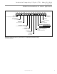
R e s i d e n t i a l Tr a n q u i l i t y ® 2 7 S p l i t ( T T S ) - 6 0 H z H F C - 4 1 0 A R e v. : 8 M a y, 2 0 1 4 C Electrical - Low Voltage Wiring Thermostat Connections (Indoor Compresor Section) The thermostat should be wired directly to the CXM board. Figure 21 show low voltage wiring. Note that the air handler or furnace transformer will be used to power the CXM board in the compressor section. See “Electrical – Thermostat” for specific terminal connections.
R e s i d e n t i a l Tr a n q u i l i t y ® 2 7 S p l i t ( T T S ) - 6 0 H z H F C - 4 1 0 A R e v.
R e s i d e n t i a l Tr a n q u i l i t y ® 2 7 S p l i t ( T T S ) - 6 0 H z H F C - 4 1 0 A R e v. : 8 M a y, 2 0 1 4 C Electrical - Low Voltage Wiring Note: This valve can overheat the anticipator of an electromechanical thermostat. Therefore, only relay or triac based thermostats should be used.
R e s i d e n t i a l Tr a n q u i l i t y ® 2 7 S p l i t ( T T S ) - 6 0 H z H F C - 4 1 0 A R e v.
R e s i d e n t i a l Tr a n q u i l i t y ® 2 7 S p l i t ( T T S ) - 6 0 H z H F C - 4 1 0 A R e v.
R e s i d e n t i a l Tr a n q u i l i t y ® 2 7 S p l i t ( T T S ) - 6 0 H z H F C - 4 1 0 A R e v. : 8 M a y, 2 0 1 4 C CXM Controls CXM Control For detailed control information, see CXM Application, Operation and Maintenance (AOM) manual (part #97B0003N12). Field Selectable Inputs Test mode: Test mode allows the service technician to check the operation of the control in a timely manner.
R e s i d e n t i a l Tr a n q u i l i t y ® 2 7 S p l i t ( T T S ) - 6 0 H z H F C - 4 1 0 A R e v. : 8 M a y, 2 0 1 4 C CXM Controls Safety Features – CXM Control The safety features below are provided to protect the compressor, heat exchangers, wiring and other components from damage caused by operation outside of design conditions. Anti-short cycle protection: The control features a 5 minute anti-short cycle protection for the compressor. Note: The 5 minute anti-short cycle also occurs at power up.
R e s i d e n t i a l Tr a n q u i l i t y ® 2 7 S p l i t ( T T S ) - 6 0 H z H F C - 4 1 0 A R e v. : 8 M a y, 2 0 1 4 C CXM Controls CXM Control Start-up Operation Table 12: Nominal Resistance at Various Temperatures The control will not operate until all inputs and safety controls Resistance Resistance Temp (ºC) Temp (ºF) Temp (ºC) Temp (ºF) are checked for normal conditions. The compressor will have a (kOhm) (kOhm) -17.8 0.0 85.34 55 131.0 2.99 5 minute anti-short cycle delay at power-up.
R e s i d e n t i a l Tr a n q u i l i t y ® 2 7 S p l i t ( T T S ) - 6 0 H z H F C - 4 1 0 A R e v. : 8 M a y, 2 0 1 4 C Unit Starting and Operating Conditions Operating Limits Environment – Units are designed for indoor installation only. Never install in areas subject to freezing or where humidity levels could cause cabinet condensation (such as unconditioned spaces subject to 100% outside air). Power Supply – A voltage variation of +/– 10% of nameplate utilization voltage is acceptable.
R e s i d e n t i a l Tr a n q u i l i t y ® 2 7 S p l i t ( T T S ) - 6 0 H z H F C - 4 1 0 A R e v. : 8 M a y, 2 0 1 4 C Unit Starting and Operating Conditions Unit and System Checkout BEFORE POWERING SYSTEM, please check the following: UNIT CHECKOUT Balancing/shutoff valves: Insure that all isolation valves are open and water control valves are wired. Line voltage and wiring: Verify that voltage is within an acceptable range for the unit and wiring and fuses/ breakers are properly sized.
R e s i d e n t i a l Tr a n q u i l i t y ® 2 7 S p l i t ( T T S ) - 6 0 H z H F C - 4 1 0 A R e v. : 8 M a y, 2 0 1 4 C Unit Start-Up Procedure blocked line. Check that the condensate trap is filled to provide a water seal. e. Refer to Table 15. Check the temperature of both entering and leaving water. If temperature is within range, proceed with the test. If temperature is outside of the operating range, check refrigerant pressures and compare to Tables 16a through 16d.
R e s i d e n t i a l Tr a n q u i l i t y ® 2 7 S p l i t ( T T S ) - 6 0 H z H F C - 4 1 0 A R e v. : 8 M a y, 2 0 1 4 C Unit Operating Conditions Table 14: Two-Stage HFC-410A Compressor Section Coax Water Pressure Drop Model 026 038 049 064 GPM 2.3 3.0 3.4 4.5 6.0 3.0 4.5 6.0 6.8 9.0 4.5 6.0 6.8 9.0 12.0 6.0 7.5 9.0 11.3 12.0 15.0 Table 15: Water Temperature Change Through Heat Exchanger Pressure Drop (psi) 30°F 0.7 1.1 1.3 2.0 3.1 1.5 2.6 3.8 4.5 6.9 0.8 1.3 1.6 2.7 4.6 0.9 1.7 2.5 3.7 4.1 6.
R e s i d e n t i a l Tr a n q u i l i t y ® 2 7 S p l i t ( T T S ) - 6 0 H z H F C - 4 1 0 A R e v.
R e s i d e n t i a l Tr a n q u i l i t y ® 2 7 S p l i t ( T T S ) - 6 0 H z H F C - 4 1 0 A R e v. : 8 M a y, 2 0 1 4 C Preventive Maintenance Water Coil Maintenance (Direct ground water applications only) If the system is installed in an area with a known high mineral content (125 P.P.M. or greater) in the water, it is best to establish a periodic maintenance schedule with the owner so the coil can be checked regularly.
R e s i d e n t i a l Tr a n q u i l i t y ® 2 7 S p l i t ( T T S ) - 6 0 H z H F C - 4 1 0 A R e v. : 8 M a y, 2 0 1 4 C Troubleshooting General If operational difficulties are encountered, perform the preliminary checks below before referring to the troubleshooting charts. • Verify that the unit is receiving electrical supply power. • Make sure the fuses in the fused disconnect switches are intact.
R e s i d e n t i a l Tr a n q u i l i t y ® 2 7 S p l i t ( T T S ) - 6 0 H z H F C - 4 1 0 A R e v. : 8 M a y, 2 0 1 4 C CXM Process Flow Chart WARNING! WARNING! HAZARDOUS VOLTAGE! DISCONNECT ALL ELECTRIC POWER INCLUDING REMOTE DISCONNECTS BEFORE SERVICING. Failure to disconnect power before servicing can cause severe personal injury or death.
R e s i d e n t i a l Tr a n q u i l i t y ® 2 7 S p l i t ( T T S ) - 6 0 H z H F C - 4 1 0 A R e v. : 8 M a y, 2 0 1 4 C Functional Troubleshooting Fault Main power problems HP Fault Code 2 Htg Clg Possible Cause Solution Air temperature out of range in heating Overcharged with refrigerant Bad HP Switch Insufficient charge Check line voltage circuit breaker and disconnect. Check for line voltage between L1 and L2 on the contactor.
R e s i d e n t i a l Tr a n q u i l i t y ® 2 7 S p l i t ( T T S ) - 6 0 H z H F C - 4 1 0 A R e v. : 8 M a y, 2 0 1 4 C Functional Troubleshooting Unit Doesn’t Operate in Cooling X Reversing valve X X Thermostat setup Thermostat wiring X Thermostat wiring Set for cooling demand and check 24VAC on RV coil and at CXM/DXM board. If RV is stuck, run high pressure up by reducing water flow and while operating engage and disengage RV coil voltage to push valve. Check for ‘O’ RV setup not ‘B’.
R e s i d e n t i a l Tr a n q u i l i t y ® 2 7 S p l i t ( T T S ) - 6 0 H z H F C - 4 1 0 A R e v.
Geothermal Heating and Cooling 3OHDVH UHIHU WR WKH &0 ,QVWDOODWLRQ 2SHUDWLRQ DQG 0DLQWHQDQFH 0DQXDO IRU RSHUDWLQJ DQG PDLQWHQDQFH LQVWUXFWLRQV 5HY 3DUW 1R 53 127( 6RPH VWDWHV RU &DQDGLDQ SURYLQFHV GR QRW DOORZ OLPLWDWLRQV RQ KRZ ORQJ DQ LPSOLHG ZDUUDQW\ ODVWV RU WKH OLPLWDWLRQ RU H[FOXVLRQV RI FRQVHTXHQWLDO RU LQFLGHQWDO GDPDJHV VR WKH IRUHJRLQJ H[FOXVLRQV DQG OLPLWDWLRQV PD\ QRW DSSO\ WR \RX 7KLV ZDUUDQW\ JLYHV \RX VSHFL¿F OHJDO ULJKWV DQG \RX PD\ DOVR KDYH RWKHU ULJKWV ZKLFK YD
R e s i d e n t i a l Tr a n q u i l i t y ® 2 7 S p l i t ( T T S ) - 6 0 H z H F C - 4 1 0 A R e v. : 8 M a y, 2 0 1 4 C Notes c l i m a t e m a s t e r.
R e s i d e n t i a l Tr a n q u i l i t y ® 2 7 S p l i t ( T T S ) - 6 0 H z H F C - 4 1 0 A R e v. : 8 M a y, 2 0 1 4 C Revision History Date Page # Description 43-44 Updated Functional Troubleshooting Table 15, 38 Updated Tables 5 and 14 8 May, 14 All Removed TTP, Updated TTS to Rev. C 10 Jan., 13 14 Antifreeze Percentage Table Updated 17 Nov.