
Specifications
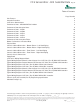


ClimateMaster works continually to improve its products. As a result, the design and specifi cations of each product at the time of order may be changed without notice and may not be as described herein. Please contact ClimateMaster's Customer
Service Department at 1-405-745-6000 for specifi c information on the current design and specifi cations. Statements and other information contained herein are not express warranties and do not form the basis of any bargain between the parties,
but are merely ClimateMaster's opinion or commendation of its products. The latest version of this document is available at climatemaster.com.
Page ______ of ______Rev.: 20 May, 2009BLC291 - 6
CCE Series 60Hz - R22 Submittal Data Eng/I-P
Geothermal Heat Pump Systems
Step 1 Determine the actual heating and cooling loads at the
desired dry bulb and wet bulb conditions.
Step 2
Obtain the following de sign parameters: Entering water
temperature, water fl ow rate in GPM, air fl ow in CFM,
water fl ow pressure drop and design wet and dry bulb
temperatures. Air fl ow CFM should be between 300
and 450 CFM per ton. Unit water pressure drop should
be kept as close as possible to each other to make
water balancing easier. Go to the ap pro pri ate tables
and fi nd the proper indicated water fl ow and water
tem per a ture.
Step 3 Select a unit based on total and sensible cooling
conditions. Select a unit which is closest to, but no
larger than, the actual cooling load.
Step 4 Enter tables at the design water fl ow and water
temperature. Read the total and sensible cooling
capacities (Note: interpolation is per mis si ble,
ex trap o la tion is not).
Step 5 Read the heating capacity. If it exceeds the design
criteria it is acceptable. It is quite normal for Water-
Source Heat Pumps to be selected on cooling capacity
only since the heating output is usually greater than
the cooling capacity.
Step 6 Determine the correction factors associated with the
variable factors of dry bulb and wet bulb.
Corrected Total Cooling =
tabulated total cooling x wet bulb correction.
Corrected Sensible Cooling =
tabulated sensible cooling x wet/dry bulb correction.
Step 7 Compare the corrected capacities to the load
re quire ments. Normally if the capacities are within 10%
of the loads, the equipment is ac cept able. It is better
to undersize than oversize, as undersizing improves
humidity control, reduces sound levels and extends the
life of the equip ment.
Step 8 When completed, calculate water temperature rise
and assess the selection. If the units selected are not
within 10% of the load cal cu la tions, then review what
effect chang ing the GPM, water temperature and/or air
fl ow and air tem per a ture would have on the corrected
capacities. If the desired capacity cannot be achieved,
select the next larger or smaller unit and repeat the
procedure. Remember, when in doubt, undersize
slightly for best performance.
Example Equipment Selection For Cool ing
Step 1 Load Determination:
Assume we have determined that the appropriate cooling
load at the desired dry bulb 80°F and wet bulb 65°F
con di tions is as follows:
Total Cooling ......................................11,500 BTUH
Sensible Cooling ...................................9,000 BTUH
Entering Air Temp ... 80°F Dry Bulb / 65°F Wet Bulb
Step 2 Design Conditions:
Similarly, we have also obtained the following design
pa ram e ters:
Entering Water Temp ....................................... 90°F
Water Flow (Based upon 12°F rise in temp.) 2.3 GPM
Air Flow ....................................................350 CFM
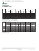
Step 3, 4 & 5 HP Selection:
After making our preliminary selection (CCE12), we enter the
tables at design water fl ow and water tem per a ture and read
Total Cooling, Sens. Cooling and Heat of Rej. ca pac i ties:
Total Cooling .......................................12,000 BTUH
Sensible Cooling ...................................8,800 BTUH
Heat of Rejection ................................15,000 BTUH
Step 6 & 7 Entering Air and Airfl ow Corrections:
Next, we determine our correction factors.
Table Ent Air Air Flow Cor rect ed
Corrected Total Cooling = 12,000 x 0.964 x 1.000 = 11,568
Corrected Sens Cooling = 8,800 x 1.085 x 1.000 = 9,548
Corrected Heat of Reject = 15,800 x 0.967 x 1.000 = 15,279
Step 8 Water Temperature Rise Calculation & As sess ment:
Actual Temperature Rise 13.2°F
When we compare the Corrected Total Cooling and Corrected
Sensible Cooling fi gures with our load re quire ments stated
in Step 1, we discover that our selection is within +/- 10%
of our sensible load requirement. Fur ther more, we see that
our Cor rect ed Total Cooling fi gure is slightly undersized as
recommended, when compared to the actual in di cat ed load.
Selection Procedure