
Specifications


ClimateMaster works continually to improve its products. As a result, the design and specifi cations of each product at the time of order may be changed without notice and may not be as described herein. Please contact ClimateMaster's Customer
Service Department at 1-405-745-6000 for specifi c information on the current design and specifi cations. Statements and other information contained herein are not express warranties and do not form the basis of any bargain between the parties,
but are merely ClimateMaster's opinion or commendation of its products. The latest version of this document is available at climatemaster.com.
Page ______ of ______Rev.: 20 May, 2009BLC291 - 35
CCE Series 60Hz - R22 Submittal Data Eng/I-P
Geothermal Heat Pump Systems
Option: Threaded EPT copper fi ttings (sweat connections are standard).
Option: Threaded IPT copper fi ttings (sweat connections are standard).
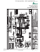
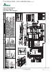
Drain Pan:
The drain pan shall be constructed of galvanized steel and have a powder coat paint application to further inhibit corrosion. This
corrosion protection system shall meet the stringent 1000 hour salt spray test per ASTM B117. If plastic type material is used,
it must be HDPE (High Density Polyethylene) to avoid thermal cycling shock stress failure over the lifetime of the unit. Stainless
Steel materials are also acceptable. Drain pan shall be fully insulated. Drain outlet shall be located at pan as to allow complete
and unobstructed drainage of condensate. The unit as standard will be supplied with solid-state electronic condensate overfl ow
protection. Mechanical fl oat switches will NOT be accepted.
Electrical:
Unit controls shall be located under the hinged control door in the sloped top grille. Operating controls shall consist of slide
switches to select “OFF”, “HEAT,” “COOL,” “AUTO” (when equipped with auto change-over option – “AUTO” is not available
for standard manual change-over controls), Fan “AUTO” (fan cycles with compressor), Fan “ON” (continuous fan), Fan “LO”,
and Fan “HI”. Temperature adjustment shall be accomplished via two push buttons, one labeled with an arrow up, and the other
labeled with an arrow down. Controls shall include an LCD display for display of temperature and set point. Units without an LCD
display shall not be accepted.
A control box shall be located above the unit compressor compartment and shall contain operating controls as outlined in the
paragraph above, 24VAC transformer, double-pole compressor relay, and solid-state controller for complete unit operation.
Reversing valve and fan motor wiring shall be routed through this electronic controller. Units shall be name-plated for use with time
delay fuses or HACR circuit breakers. A unit-mounted digital thermostat with a remote bulb measuring return air temperature shall
control the compressor operation for heating and cooling. Control shall be equipped with a fan switch (provides options to cycle fan
with compressor or provide continuous fan) and a fault indicator light. Units without a fault indicator light shall not be accepted.
Option: Digital ACO unit mounted thermostat (MCO is standard).
Option: Provisions for remote thermostat (unit mounted is standard).
Option: Disconnect Switch, Non-Fused.
Option: Disconnect Switch, Fused with 15A or 20A fuse.
Option: 20A power plug/cord.
Option: 20A plug / cord, receptacle, disconnect switch, fused with 15A or 20A fuse.
Option: 20A plug / cord, receptacle, disconnect switch, non fused.
Solid State Control System (CXM):
Units shall have a solid-state control system. Units utilizing electro-mechanical control shall not be acceptable. The control
system microprocessor board shall be specifi cally designed to protect against building electrical system noise contamination,
EMI, and RFI interference. The control system shall interface with a heat pump type thermostat. The control system shall have the
following features:
a. Anti-short cycle time delay on compressor operation.
b. Random start on power up mode.
c. Low voltage protection.
d. High voltage protection.
e. Unit shutdown on high or low refrigerant pressures.
f. Unit shutdown on low water temperature.
g. Condensate overfl ow electronic protection.
h. Option to reset unit at thermostat or disconnect.
i. Automatic intelligent reset. Unit shall automatically reset the unit 5 minutes after trip if the fault has cleared. If a fault occurs
3 times sequentially without thermostat meeting temperature, then lockout requiring manual reset will occur.
j. Ability to defeat time delays for servicing.
Console (CCE) Series 60Hz
Engineering Specifi cations Rev.: 05/20/09 Page 3