
Specifications


ClimateMaster works continually to improve its products. As a result, the design and specifi cations of each product at the time of order may be changed without notice and may not be as described herein. Please contact ClimateMaster's Customer
Service Department at 1-405-745-6000 for specifi c information on the current design and specifi cations. Statements and other information contained herein are not express warranties and do not form the basis of any bargain between the parties,
but are merely ClimateMaster's opinion or commendation of its products. The latest version of this document is available at climatemaster.com.
Page ______ of ______Rev.: 20 May, 2009BLC291 - 34
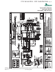
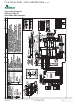
CCE Series 60Hz - R22 Submittal Data Eng/I-P
Geothermal Heat Pump Systems
induced high noise levels associated with “hard wire belly band” motor mounting. The airfl ow rating of the unit shall be based on
a wet coil and a clean fi lter in place. Ratings based on a dry coil and / or no fi lter shall NOT be acceptable.
Refrigerant Circuit:
Units shall have a sealed refrigerant circuit including a high effi ciency rotary compressor designed for heat pump operation,
a thermostatic expansion valve for refrigerant metering, an enhanced corrugated aluminum lanced fi n and rifl ed copper tube
refrigerant to air heat exchanger, reversing valve, coaxial (tube in tube) refrigerant to water heat exchanger, and safety controls
including a high pressure switch, low pressure switch (loss of charge), water coil low temperature sensor, and air coil low
temperature sensor. Access fi ttings shall be factory installed on high and low pressure refrigerant lines to facilitate fi eld service.
Activation of any safety device shall prevent compressor operation via a microprocessor lockout circuit. The lockout circuit shall be
reset at the thermostat or at the contractor supplied disconnect switch. Units that cannot be reset at the thermostat shall not
be acceptable.
Hermetic compressors shall be internally sprung. The compressor shall have a dual level vibration isolation system. The
compressor will be mounted on computer selected vibration isolation grommets to a large heavy gauge compressor mounting
tray plate, which is then isolated from the cabinet base with rubber grommets for maximized vibration attenuation. Compressor
shall have thermal overload protection. Compressor shall be located in an insulated compartment away from air stream to
minimize sound transmission.
Refrigerant to air heat exchangers shall utilize enhanced corrugated lanced aluminum fi ns and rifl ed copper tube construction
rated to withstand 450 PSIG (3101 kPa) refrigerant working pressure. Refrigerant to water heat exchangers shall be of copper
inner water tube and steel refrigerant outer tube design, rated to withstand 450 PSIG (3101 kPa) working refrigerant pressure and
450 PSIG (3101 kPa) working water pressure. The refrigerant to water heat exchanger shall be “electro-coated” with a low cure
cathodic epoxy material a minimum of 0.4 mils thick (0.4 – 1.5 mils range) on all surfaces. The black colored coating shall provide
a minimum of 1000 hours salt spray protection per ASTM B117-97 on all external steel and copper tubing. The material shall be
formulated without the inclusion of any heavy metals and shall exhibit a pencil hardness of 2H (ASTM D3363-92A), crosshatch
adhesion of 4B-5B (ASTM D3359-95), and impact resistance of 160 in-lbs (184 kg-cm) direct (ASTM D2794-93).
Refrigerant metering shall be accomplished by thermostatic expansion valve only. Expansion valves shall be dual port balanced
types with external equalizer for optimum refrigerant metering. Units shall be designed and tested for operating ranges of
entering water temperatures from 20° to 110°F (-6.7° to 43.3°C). Reversing valve shall be four-way solenoid activated refrigerant
valve, which shall default to heating mode should the solenoid fail to function. If the reversing valve solenoid defaults to cooling
mode, an additional low temperature thermostat must be provided to prevent over-cooling an already cold room.
Option: The unit will be supplied with cupro nickel coaxial water to refrigerant heat exchanger.
Option: The unit will be supplied with internally factory mounted two-way water valve for variable speed pumping requirements.
A factory-mounted or fi eld-installed high pressure switch shall be installed in the water piping to disable compressor
operation in the event water pressures build due to water freezing in the piping system.
Option: The unit will be supplied with internally factory mounted automatic water fl ow regulators.
Option: The unit will be supplied with internally mounted secondary pump for primary/secondary applications, specifi cally one-
pipe systems.
Option: The unit shall be supplied with extended range Insulation option, which adds closed cell insulation to internal water lines,
and provides insulation on suction side refrigeration tubing including refrigerant to water heat exchanger.
Option: The refrigerant to air heat exchanger shall be “electro-coated” with a low cure cathodic epoxy material a minimum of 0.4
mils thick (0.4 – 1.5 mils range) on all surfaces. The black colored coating shall provide a minimum of 1000 hours salt spray
protection per ASTM B117-97 on all galvanized end plates and copper tubing, and a minimum of 2000 hours of salt spray
on all aluminum fi ns. The material shall be formulated without the inclusion of any heavy metals and shall exhibit a pencil
hardness of 2H (ASTM D3363-92A), crosshatch adhesion of 4B-5B (ASTM D3359-95), and impact resistance of 160 in-lbs
(184 kg-cm) direct (ASTM D2794-93).
Piping:
Water piping shall terminate in the same location regardless of the connection and valve options.
Console (CCE) Series 60Hz
Engineering Specifi cations Rev.: 05/20/09 Page 2