
Specifications


ClimateMaster works continually to improve its products. As a result, the design and specifi cations of each product at the time of order may be changed without notice and may not be as described herein. Please contact ClimateMaster's Customer
Service Department at 1-405-745-6000 for specifi c information on the current design and specifi cations. Statements and other information contained herein are not express warranties and do not form the basis of any bargain between the parties,
but are merely ClimateMaster's opinion or commendation of its products. The latest version of this document is available at climatemaster.com.
Page ______ of ______Rev.: 20 May, 2009BLC291 - 33
CCE Series 60Hz - R22 Submittal Data Eng/I-P
Geothermal Heat Pump Systems
General:
Furnish and install ClimateMaster “Console” Water Source Heat Pumps, as indicated on the plans. Equipment shall be completely
assembled, piped and internally wired. Capacities and characteristics as listed in the schedule and the specifi cations that follow.
Console Water Source Heat Pumps:
Units shall be supplied completely factory built for an entering water temperature range from 20º to 110ºF (-6.7º to 43.3ºC) as
standard. Equivalent units from other manufacturers can be proposed provided approval to bid is given 10 days prior to bid
closing. All equipment listed in this section must be rated and certifi ed in accordance with American Refrigeration Institute /
International Standards Organization (ARI / ISO) and Environmental Testing Laboratories for United States and Canada (ETL-US-C).
The units shall have ARI / ISO and ETL-US-C labels.
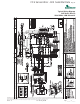
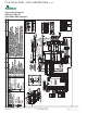
Basic Construction:
Console Units shall have one of the following air fl ow and piping arrangements: Front Inlet/Right-hand Piping; Front Inlet/
Left-hand piping; Bottom Inlet/Right-hand piping; or Bottom Inlet/Left-hand piping as shown on the plans. If units with
these arrangements are NOT used, the contractor is responsible for any extra costs incurred by other trades. If other
arrangements make servicing diffi cult, the contractor must provide access panels and clear routes to ease service. Architect/
Engineer must approve any changes in layout.
The cabinet, wall mounting hardware and subbase shall be constructed of heavy gauge galvanized steel with a baked polyester
powder coat paint fi nish. Corrosion protection system shall meet the stringent 1000 hour salt spray test per ASTM B117. Unit
corrosion protection must meet these stringent requirements or unit(s) will not be accepted. Color will be Polar Ice. Both sides
of the steel shall be painted for added protection. Additionally, the wall mounting hardware shall have welded corner bracing. The
easily removable cabinet enclosure allows for easy service to the chassis, piping compartment and control compartment.
All interior surfaces shall be lined with 1/4 inch (6.4mm) thick, dual density, 2 lb/ft3 (32 kg/m3) acoustic fl exible blanket type glass
fi ber insulation with a non-woven, anti-microbial treated mat face. Insulation placement shall be designed in a manner that will
eliminate any exposed edges to prevent the introduction of glass fi bers into the air stream.
Standard insulation must meet NFPA Fire Hazard Classifi cation requirements 25/50 per ASTM E84, UL 723, CAN/ULC S102-M88
and NFPA 90A requirements; air erosion and mold growth limits of UL-181; stringent fungal resistance test per ASTM-C1071 and
ASTM G21; and shall meet zero level bacteria growth per ASTM G22. Unit insulation must meet these stringent requirements
or unit(s) will not be accepted.
The cabinet shall have a 30º sloped top with aluminum rigid bar type discharge grille. Aluminum discharge grille shall be
anodized charcoal grey in color including hinged control door. Cabinet shall have rounded edges (0.325 inch / 8.255 mm
minimum radius) on all exposed corners for safety and esthetic purposes. Units not having sloped top and rounded corners
(0.325 inch / 8.255 mm minimum) on front, side, top slope, and top corners shall not be accepted.
Return Air Filter shall be 3/8” (9.5mm) permanent cleanable media type or 1/8” (3.2mm) for front return type units.
Option: The unit shall be provided with a keyed lock on the control access door.
Option: The unit shall be provided with a motorized outside air damper and damper assembly, factory mounted and wired.
Option: The unit shall be provided with a 5 inch (127mm) high subbase (3 inch / 76.2mm subbase is standard).
Option: The unit shall be provided without a subbase (3 inch / 76.2mm high subbase is standard).
Option: The unit shall include a front return air grille integrally stamped into Cabinet (no subbase allowed).
Option: The unit shall be supplied with extended range Insulation option, which adds closed cell insulation to internal water lines,
and provides insulation on suction side refrigeration tubing including refrigerant to water heat exchanger.
Fan and Motor Assembly:
Fan and motor assembly shall be assembled on a slide out fan deck with quick electrical disconnecting means to provide and
facilitate easy fi eld servicing. The fan motor shall be multi-speed, permanently lubricated, PSC type, with internal thermal
overload protection. Units supplied without permanently lubricated motors must provide external oilers for easy service. The fan
motor shall include a torsionally fl exible motor mounting system or saddle mount system with resilient rings to inhibit vibration
Console (CCE) Series 60Hz
Engineering Specifi cations Rev.: 05/20/09 Page 1