
Specifications


ClimateMaster works continually to improve its products. As a result, the design and specifi cations of each product at the time of order may be changed without notice and may not be as described herein. Please contact ClimateMaster's Customer
Service Department at 1-405-745-6000 for specifi c information on the current design and specifi cations. Statements and other information contained herein are not express warranties and do not form the basis of any bargain between the parties,
but are merely ClimateMaster's opinion or commendation of its products. The latest version of this document is available at climatemaster.com.
Page ______ of ______Rev.: 20 May, 2009BLC291 - 3
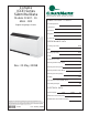
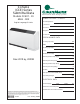
CCE Series 60Hz - R22 Submittal Data Eng/I-P
Geothermal Heat Pump Systems
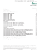
Table of Contents
*Page Number
Unit Features 4
Selection Procedure 5
CCE Series Nomenclature 7
Performance Data - ARI/ASHRAE/ISO 13256-1 8
Performance Data Selection Notes 9
Performance Data - CCE07 10
Performance Data - CCE09 11
Performance Data - CCE12 12
Performance Data - CCE15 13
Performance Data - CCE19 14
Performance Data Correction Tables 15
Blower Performance & Electrical Data 16
Physical Data 17
Console Cabinet Dimensions - Bottom Return - Left Hand Piping 18
Console Cabinet Dimensions - Bottom Return - Right Hand Piping 19
Console Cabinet Dimensions - Front Return - Left Hand Piping 20
Console Cabinet Dimensions - Front Return - Right Hand Piping 21
Console Chassis Dimensions 22
Piping Detail 23
CCE Series Wiring Diagram Matrix 24
Typical Wiring Diagram Manual & Auto Change Over CCE Units (Rev. B) With CXM Controller 25
Typical Wiring Diagram Remote Mounted Thermostat CCE Units (Rev. B) With CXM Controller 26
Typical Wiring Diagram CCE Units (Rev. B) With CXM & LON Controller 27
Typical Wiring Diagram CCE Units (Rev. B) With CXM & MPC Controller 28
Typical Wiring Diagram Manual & Auto Change Over CCE Units (Rev. B) With DXM Controller 29
Typical Wiring Diagram Remote Mounted Thermostat CCE Units (Rev. B) With DXM Controller 30
Typical Wiring Diagram CCE Units (Rev. B) With DXM & LON Controller 31
Typical Wiring Diagram CCE Units (Rev. B) With DXM & MPC Controller 32
Console (CCE) Series 60Hz (Rev. B) Engineering Specifications 33
Submittal Change Log 40
*Document page number is shown next to part number (e.g. LC291 - 3 = page 3). Since not all pages are typically used in the
submittals process, the page number in the lower right corner can still be used (page ____of_____).