
Specifications


16
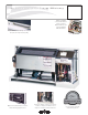
ClimateMaster Water-Source Heat Pumps
Console (CCE) Series
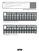
0.5 to 1.5 Ton Console Units
Air Flow Water Flow Ext Static Pressure Water Pressure Drop
Airflow (L/s) = CFM x 0.472 Water Flow (L/s) = gpm x 0.0631 ESP (Pa) = ESP (in of wg) x 249 PD (kPa) = PD (ft of hd) x 2.99
Reference Calculations
BTUH = BTU( British Thermal Unit) per hour
CFM = airfl ow, cubic feet/minute
COP = coeffi cient of performance = BTUH output/BTUH input
DB = dry bulb temperature (°F)
EAT = entering air temperature, Fahrenheit (dry bulb/wet bulb)
EER = energy effi ciency ratio = BTUH output/Watt input
ESP = external static pressure (inches w.g.)
EWT = entering water temperature
GPM = water fl ow in U.S. gallons/minute
HE = total heat of extraction, BTUH
HC = air heating capacity, BTUH
HR = total heat of rejection, BTUH
HWC = hot water generator (desuperheater) capacity, Mbtuh
KW = total power unit input, kilowatts
LAT = leaving air temperature, °F
LC = latent cooling capacity, BTUH
LWT = leaving water temperature, °F
MBTUH = 1000 BTU per hour
S/T = sensible to total cooling ratio
SC = sensible cooling capacity, BTUH
TC = total cooling capacity, BTUH
WB = wet bulb temperature (°F)
WPD = waterside pressure drop (psi & ft. of hd.)
Conversion Table - to convert inch-pound (English) to SI (Metric)
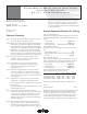
Legend and Glossary of Abbreviations
LWT = EWT -
HE
GPM x 500
LAT = EAT +
HC
CFM x1.08
LWT = EWT +
HR
GPM x 500
LAT (DB) = EAT (DB) -
SC
CFM x1.08
LC = TC - SC
S/T =
SC
TC
Heating
Cooling
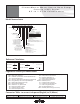
Model Nomenclature
C C E AA0 7 CG S S C S R S
94 5 6
7
8 101112131415
CCE = Console
Power Termination
Revision Level
Voltage
Controls
M = Bottom Return w/UltraQuiet
Cabinet Insulation
L = Bottom Return w/Locking Control Door
Subbase
A = Copper Water Coil w/E-Coated Air Coil
Heat Exchanger Options
C = Copper Water Coil
J = Cupro-Nickel Water Coil w/E-Coated Air Coil
N = Cupro-Nickel Water Coil
R = Right Piping
Piping Connections
L = Left Piping
Standard
D = Bottom Return w/Locking Control Door & UltraQuiet
F = Front Return
S = Bottom Return
B = Front Return w/UltraQuiet
D = 3” Subbase w/Motorized Damper
G = 5” Subbase
S = 3” Subbase
H = 5” Subbase w/Motorized Damper
N = None
V = Copper Water Coil w/E-Coated Air Coil & Extended Range Insulation
E = Copper Water Coil w/Extended Range Insulation
M = Cupro-nickel Water Coil w/E-Coated Air Coil & Extended Range Insulation
F = Cupro-nickel Water Coil w/Extended Range Insulation
1 2 3
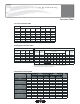
S = Standard
None S F M
Motorized Water Valve A G N
Autoflow (2.25 Gpm/Ton) B H P
Autoflow (3.0 Gpm/Ton) C J Q
Motorized Water Valve & Afr (2.25) D K R
Motorized Water Valve & Afr (3.0) E L T
Secondary Circulation Pump U V W
Water Circuit Options
G = Front Return w/Locking Control Door
E = Front Return w/Locking Control Door & UltraQuiet
N = No Cabinet Chassis Only
C = No Cabinet Chassis Only w/UltraQuiet
07
09
12
15
19
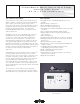
A = Electro-Mechanical Controls
Model Type
Unit Size
A = Field Connected (Hard Wire)
Sweat IPT EPT
B = Digital Display Controls
A = MCO Unit Mounted Tstat w/CXM
B = MCO Unit Mounted Tstat w/DXM
C = ACO Unit Mounted Tstat w/CXM
D = ACO Unit Mounted Tstat w/DXM
R = Remote Mounted Tstat w/CXM
S = Remote Mounted Tstat w/DXM
L = Remote Mounted w/CXM & LON
M = Remote Mounted w/DXM & LON
N = Remote Mounted w/CXM & MPC
P = Remote Mounted w/DXM & MPC
A = 115/60/1
E = 265/60/1
G = 208-230/60/1
B = 20Amp Plug & Cord
D = Disconnect Switch & 15Amp Fuse
F = Disconnect Switch (Non Fused)
H = 20Amp Plug, Cord, Receptacle,
Disconnect Switch & 15Amp Fuse
K = 20Amp Plug, Cord, Receptacle &
Disconnect Switch (Non Fused)
Rev.: 06/01/06D