
Manual
55
www.climacoolcorp.com
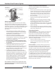
Stainless Steel Strainer Option
What Causes Water Hammer?
Any action that can cause a rapid change in the velocity
downstream valve, pump stoppage, etc. Typically, for
that are closed within 1/10
th
of a second can generate a
water hammer.
What Can Water Hammer Do?
to dangerously high values. These pressure spikes can cause
serious damage to valves, pipes, strainers, joints, etc. The
CS strainer is rated to an absolute maximum pressure of 150
psi for bolted lid models, and 125 psi for clamp lid modes.
A water hammer pressure spike that raises the pressure
higher than the maximum rated pressure may result in
strainer damage, voiding the manufacturer’s warranty.
What Prevents Water Hammer?
There are certain precautions that can be taken to prevent
relief valve and strategically located within the water
system may provide adequate protection against the
given to the design and control strategy for valves and
pumps so their actions do not invite a water hammer.
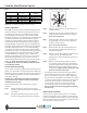
Automatic Timer Flush (ATF) Package Option
strainer’s reservoir. The power supply and timer controls for
the valve package are housed inside the ATF control box.
System Components
1.
2.
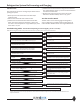
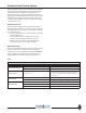
Figures 22 and 23).
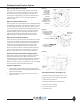
A
GREEN POINTER
INNER RING
(LENGTH OF FLUSH)
(FACTORY SET AT
8-SECONDS)
RED POINTER
OUTER RING
(TIME BETWEEN
FLUSHES)
(FACTORY SET AT
24-HOURS)
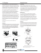
Figure 23
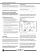
B
12VDC@2.5A POWER
FROM PDA OR 120V PLUG
IN TRANSFORMER
OPEN/CLOSE
INDICATOR
COVER-PLATE SCREWS
(4) IN CORNERS OF BOX
(TIMER BASED VALVE
CONTROLLER)
CONTROL SWITCH
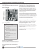
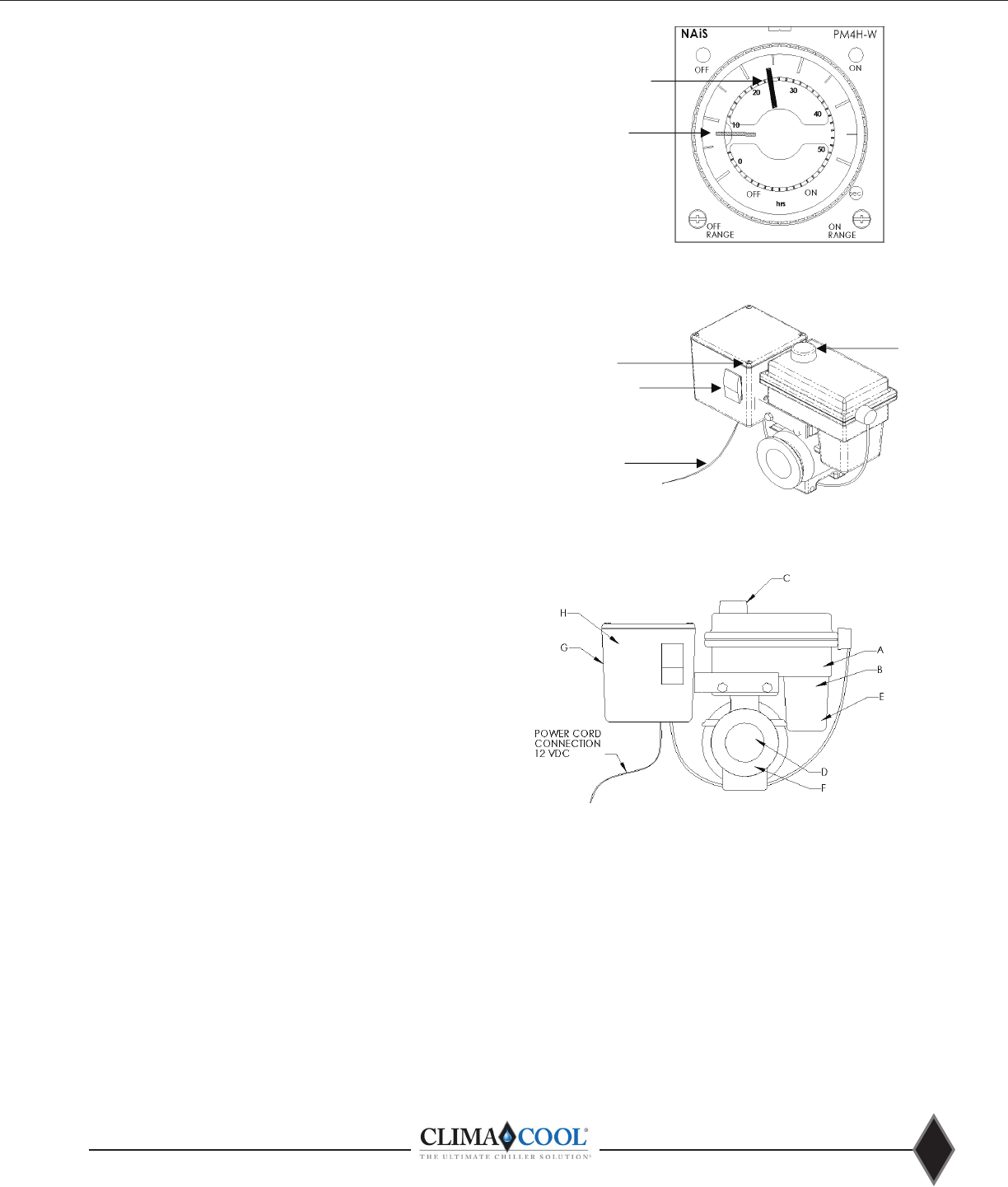
Figure 24
Valve Specications (See Figure 24)
A. Water-resistant polypropylene motor case
B. High torque motors with perma-lube gears
C. Open and close indicator
D. Stainless steel ball valve and hardware
E. Auto reset circuit breaker
F. 90
o
bidirectional rotation
G. Controller case
Figure 22