
Manual
51
www.climacoolcorp.com
Refrigeration System Re-Processing and Charging
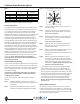
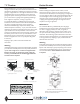
Test the Valve
The resistance of the motor winding may be tested without
opening the system.
1. Remove power from the external controller and/or
interface board.
2. Remove the valve leads from interface board.
3. Measure the resistance between the black and white
leads of the valve. Resistance should be 75 ohms with
the valve at room temperature or approximately 65 ohms
if the valve is at -40°F.
4. Measure the resistance between the green and red leads.
This value should be within ± 5% of the resistance between
the black and white leads.
5. Measure the resistance from any lead to valve body.
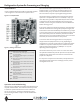
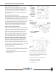
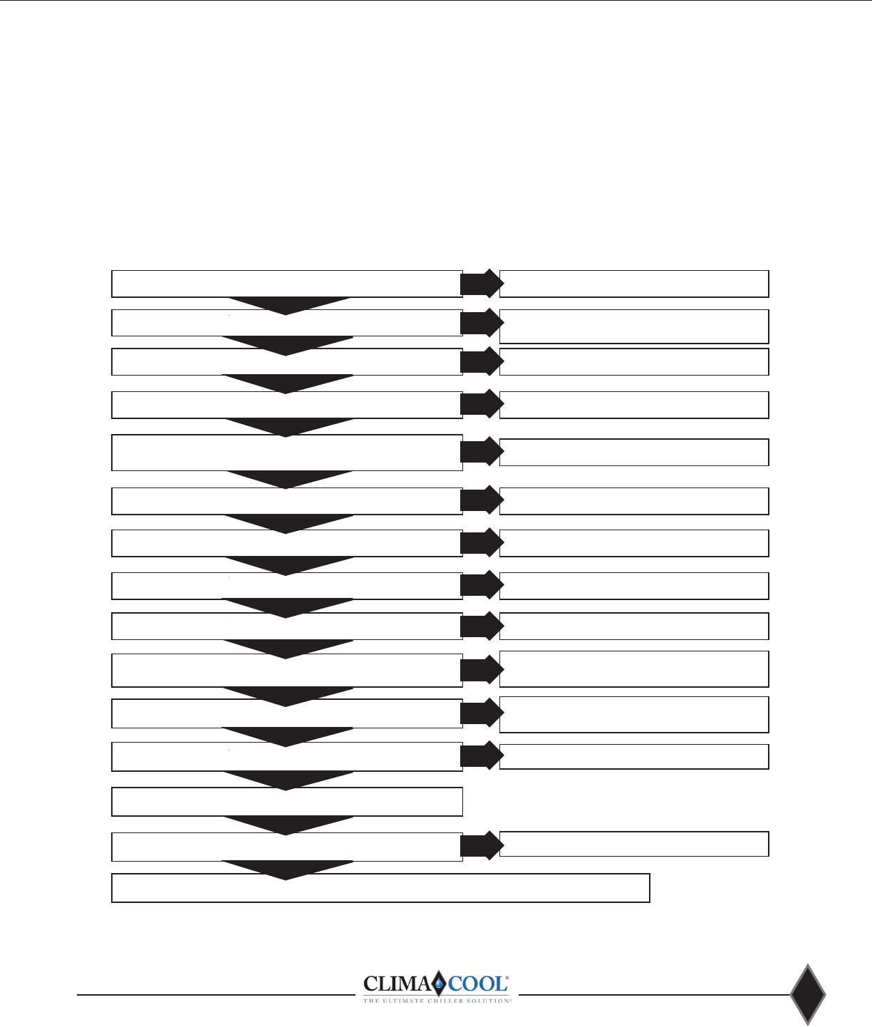
Test the Interface Board
assist in diagnosing a possible interface board failure. All
measurements should be made with a Digital Multimeter.
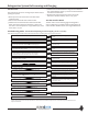
Troubeshooting Guide - Interface Board Operating on External Signal (4-20 ma or 0-10 VDC)
Note: Before testing the interface board, make certain the valve is operating. See “Test the Valve” instructions.
YES
YES
YES
YES
YES
YES
YES
YES
YES
YES
YES
YES
YES
YES
NO
NO
NO
NO
NO
NO
NO
NO
NO
NO
NO
NO
NO
Repair or replace power supply or power supply
wiring.
Check wiring for polarity. Transformer should
NOT be a grounded secondary type. Replace if
necessary.
Replace the transformer with an isolated
secondary type.
wiring.
Test the step motor. If operational, replace the
interface board.
Test the step motor. If operational, replace the
interface board.
controller. Correct input signal observing polarity.
Test or replace external controller.
controller and correct wiring.
controller and move pin jumper to correct
location.
greater than 4 ma. If so, repair wiring or replace
pumpdown relay.
Test the step motor. If operational, replace the
interface board.
Interface board if defective. Replace interface
board.
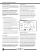
5. Connect voltmeter on AC scale to the Black and White
valve terminals . Interrupt and restore power to the
6. Repeat above test using Red and Green terminals. Does
volts DC or 0-10 VDC.
term -4-20.
11. If present, remove wires from pumpdown terminals IN &
12. Put a jumper across terminals IN & GND. Did the valve
13. Remove the jumper from terminals IN & GND and
reconnect the wires.
14. Remove the pin jumper from CN4 or CN2. Did the valve
Interface board is functional, test external controller
*Note: CN4 provides 3 levels of input impedence to match external controller outputs. Be sure controller output and interface board
inputs are matched.