
Manual

23
www.climacoolcorp.com
Startup
All startups must be performed by ClimaCool factory
trained personnel.
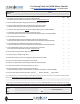
1. Review all items are complete from the Pre-Startup
Check List.
2. Cross reference model number with submittal sheet
to verify that the units are the correct model type and
voltage requirements.
3. Verify the location and wiring connections of all main
FULLY
INSERTED into their sensor wells and wired back to the
Master Control Panel.
4.
headers).
sensors back to the master controller universal input
sset for ‘volts’. Note:
NOT be piped to a location which includes strainer
pressure drops.
5.
include strainer assemblies equipped with 60 mesh
screens.
6. Inspect all refrigerant piping for oil leaks which may
have occurred during shipment which might indicate a
refrigerant leak. Check the high pressure cutout setting
of the pressure controls. The setting should be 385 psig
UGW models.
7. Verify the location and settings of the phase
loss monitor. It should be in a location to sense the
voltage condition in the main, high voltage panel which
feeds high voltage to each module independently.
Verify the low voltage output wiring from the phase loss
CoolLogic
controller, input channel 12.
8. Determine if the chiller modules are equipped with
motorized water isolation valves. If so, verify the
settings of the motorized valves auxiliary switch dial
settings, to ensure they close near:
9.
and that all VFD’s are controlling the pump speeds to
the chiller bank headers, measured precisely at the
10 psid.
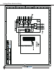
10.
and module controllers as shown on the wiring diagrams
provided on the inside electrical door panels.
• Set the rotary switches for the MAC Address of the
master controller to be “01.”
• Set the rotary switches for the module controllers to
be “02” for module #1, “03” for module #2, and so on.
11. Tighten every screw and lug connection inside the
CoolLogic master control panel and inside each module
control panel high voltage section. Check auxiliary
contacts on contactors ensure #1 auxiliary is wired on
the #1 contactor. Open up the compressor junction box
located on the front of each compressor and verify main
electrical terminal lug tightness and the low voltage
wires on protection module.
12. Verify the communication cable wiring to ensure it is
18 AWG, simple two conductor shielded cable and that
the wiring is alone inside solid conduit between the
Verify the cable’s outer jacket is not stripped more than
one inch. If so, the wires may have become untwisted,
connected correctly to the terminal blocks at the
master and each module as follows:
Black wire to Net-
White wire to Net +
Shield wire to Shield
Verify that the shield part of the wires continues the
daisy chain connection through to the last module but,
that this shield is NOT connected to a terminal lug inside
any module.
13. Power-up the master control panel and download the
following the instructions, “Install Clippings to Master.”
14. Power up each module control panel, turn OFF the two
toggle switches located on the inside bottom of the low
voltage side of the module electrical panel. Download
following the instructions, “Install Clippings to Module.”
15. Check for proper line or high voltage values at each
module input power block, and the 24 VAC low voltage
16.
tapped for the measured incoming power supply.
17. Use refrigerant gauge set suitable for R-134a, and
hook up to the suction and discharge ports of each
module’s compressor stages separately. Bump start
the compressor by using the manual run commands
the service menu). Bump the compressor only for 1-2
seconds to ensure the correct rotation of the scroll
and a falling suction pressure).