
Manual
11
www.climacoolcorp.com
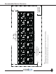
LOAD 1
FROM CHILLER BANK
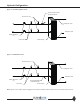
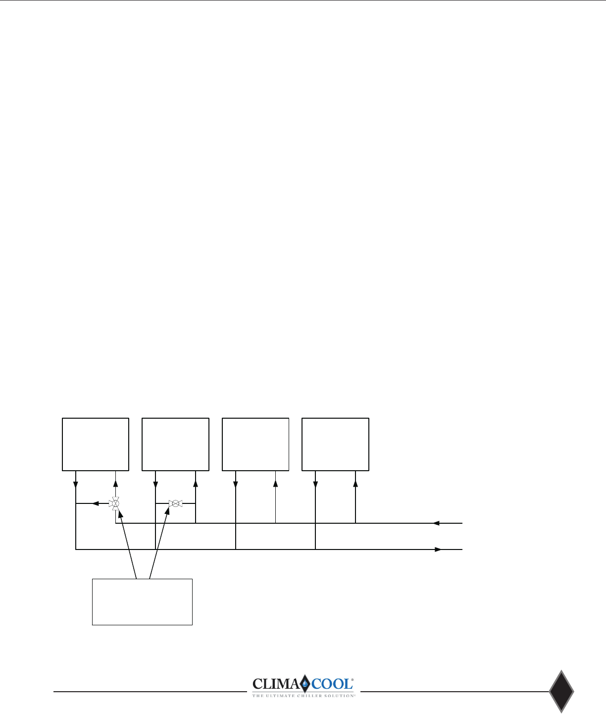
TYPICAL LOAD BYPASS VALVE ARRANGEMENT
TO CHILLER BANK
LOAD 2 LOAD 3 LOAD X
TYPICAL CHILLED AND HOT WATER
LOAD SIDE BYPASS VALVES
SIZE EQUIVALENT TO ONE MODULE
WORTH OF FLOW
Figure 8 - Typical Load Bypass Valve Arrangement
modules remaining for that duty. Also, with a module acting
as a bypass increased wear of heat exchangers may be
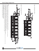
shown on page 10. The bypass kits must be installed on
each water source loop and controls are integrated with the
CoolLogic software. Installation location can be found on
The design piping must accommodate one module’s worth
bypass mode. See Figures 9 and 10 on page 12 - Water
The eld supplied piped chiller/
heater system bypass must be controlled by others. There
are system communication delays, polling and network
water/evaporator, hot water/condenser water systems.
Load Side System Bypass (Air Handlers, Fan
Coils, etc.)
A load system bypass is required for preventing pump
Examples of an acceptable load side system bypass are:
•Utilize a quantity of 3-way control valves on the largest
loads farthest from the chiller/heater system.
•Field piping with a control valve to provide a bypass across
the larger system loads when their 2-way valves go closed.
Please refer to Figure 8 for a typical load bypass
valve arrangement. The load side system bypass should
be sized for an absolute minimum of one module’s worth
A minimum of (6) six gallons per
nominal system ton are also required to maintain proper
system thermal inertia. This is to avoid short cycling of
compressors in the chiller/heater system as well as prevent
nuisance alarms.
Water Piping