
Manual
www.climacoolcorp.com
10
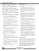
Water Piping
As with any water system, it is important that the system
be clean. The pipe work installer must remove weld scale,
rust and contamination during pipe work fabrication.
are compatible with 316 stainless steel, prior to making
connections to the ClimaCool chiller. There are certain
necessary components that should always be installed
in both the chilled water and condenser water systems.
be found on page 12. All water piping must be installed in
accordance with applicable codes and standards.
Temperature Sensor and Wells
CoolLogic Control
the bank and before the strainer on the chilled water inlet,
chilled water outlet, condenser water inlet and condenser
Note: Sensors must be fully inserted into the well to obtain
proper readings.
Pressure Dierential Flow Sensor
not exceeded. To prevent operation of the chiller without
both the chilled and condenser water circuits. Place one
on each side, downstream of the strainers on the inlet and
outlet of a straight pipe, as close to the module as possible.
Do not put in an elbow on the outlet.
Note: Evaporator and condenser
sides both require sensors of equal pressure ranges.
Pressure Taps
The installing contractor must provide access ports for
pressure gauges for both the condenser and chilled water
systems. A ¼” pressure tap is required on the inlet and the
Water Isolation Valves
It is recommended to provide bank water isolation valves
for proper isolation and maintenance of the chiller, pump
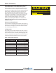
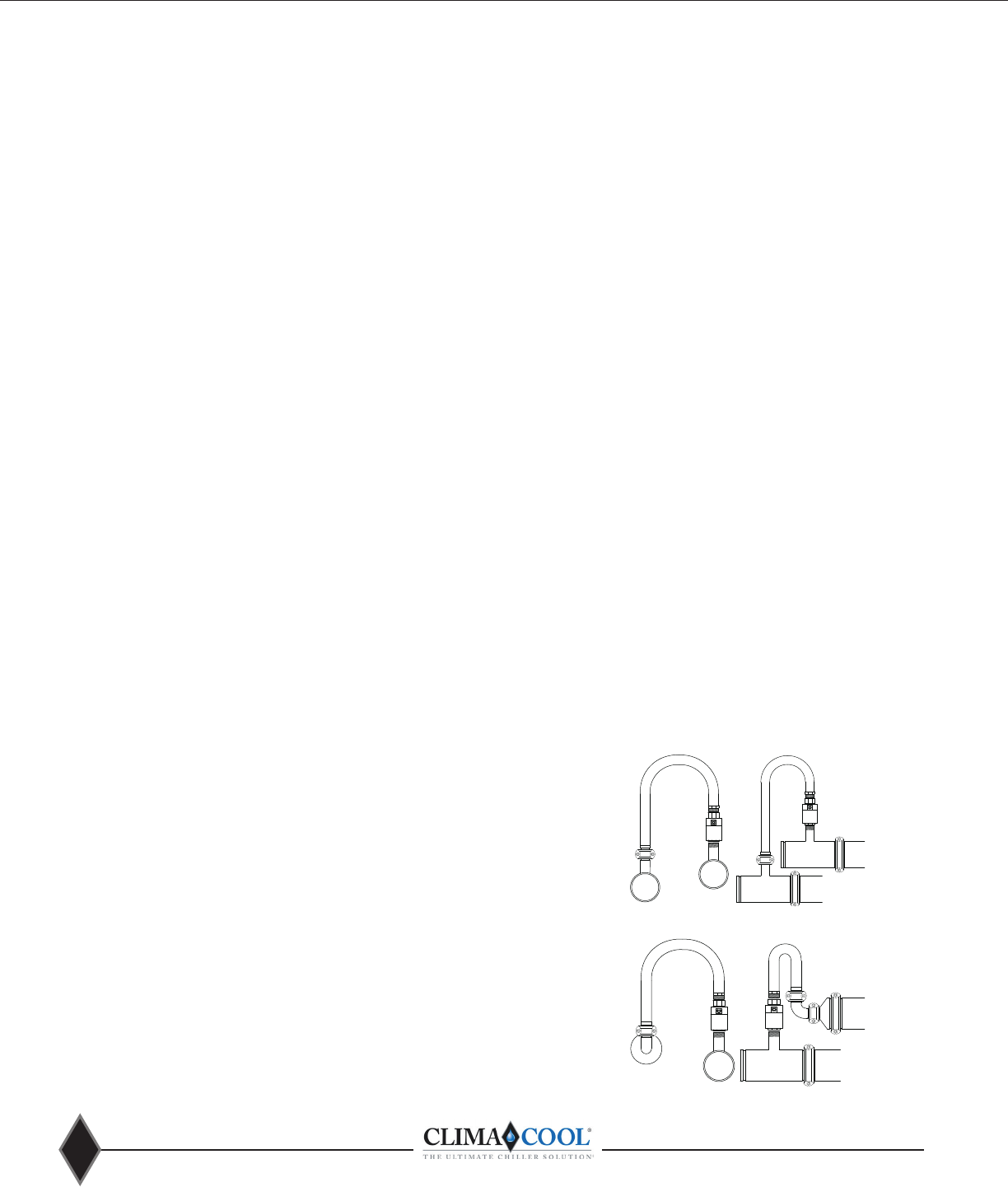
Strainers – Minimum 60 Mesh Screen Required
ClimaCool chillers utilize brazed plate heat exchangers
which are extremely sensitive to debris. Therefore, it is
mandatory that all condenser and chilled water systems
include a strainer with a minimum of 60 mesh screen for
proper ltration. The strainers must be installed as shown in
ClimaCool’s warranty does not cover and does not apply to
products which have defects or damages due to freezing
of the water supply, an inadequate or interrupted water
supply, corrosives or abrasives in the water supply, or
improper or inadequate ltration or treatment of the
water supply.
Chiller/Heater System Water Header Bypass
A bypass is required for any chilled water/evaporator, hot
variable pumping. The bypass must be piped in such a way
Figures 9 and 10 on page 12. The purpose of the chiller/
heater system bypass is to prevent deadheading of the
pumps when all of the internal unit valves go closed as well
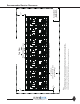
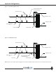
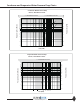
HEADER BYPASS
REVERSE RETURN
No.10
2" 90°
No.50
Reducer
6 x 2
Module
Header
No. 29 Reducing Tee
w/Thd. Branch
6 x 6 x 2
Module
Header
SIDE VIEW
6"
Grooved Coupling
6"
Grooved Coupling
2"
Grooved
Coupling
Hose Kit
2"
Grooved
Coupling
2" Belimo
Ball Valve &
Actuator
No. 29 Reducing Tee
w/Thd. Branch
6 x 6 x 2
END VIEW
No.10
2" 90°
Elbow
No.50 Reducer
6 x 2
Hose Kit
2" Belimo
Ball Valve &
Actuator
2"
Grooved
Coupling
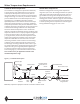
Figure 7 - Reverse Return
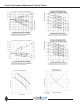
No. 25 Grooved Branch
6 x 6 x 2
Module
Header
6"
Grooved Coupling
HEADER BYPASS
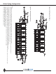
DIRECT RETURN &
SIMULTANEOUS HTG & CLG
No. 29 Reducing Tee
w/Thd. Branch
6 x 6 x 2
Module
Header
6"
Grooved Coupling
SIDE VIEW
No. 25 Grooved Branch
6 x 6 x 2
No. 29 Reducing Tee
w/Thd. Branch
6 x 6 x 2
END VIEW
Hose Kit
2" Belimo
Ball Valve &
Actuator
2"
Grooved
Coupling
2" Belimo
Ball Valve &
Actuator
Hose Kit
2"
Grooved
Coupling
No. 25 Grooved Branch
6 x 6 x 2
Module
Header
6"
Grooved Coupling
HEADER BYPASS
DIRECT RETURN &
SIMULTANEOUS HTG & CLG
No. 29 Reducing Tee
w/Thd. Branch
6 x 6 x 2
Module
Header
6"
Grooved Coupling
SIDE VIEW
No. 25 Grooved Branch
6 x 6 x 2
No. 29 Reducing Tee
w/Thd. Branch
6 x 6 x 2
END VIEW
Hose Kit
2" Belimo
Ball Valve &
Actuator
2"
Grooved
Coupling
2" Belimo
Ball Valve &
Actuator
Hose Kit
2"
Grooved
Coupling
Figure 6 - Direct Return