
Manual

www.climacoolcorp.com
66
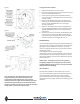
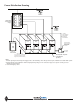
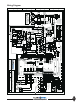
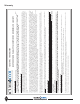
Wiring Diagram
SIZE File No.
Dwg. No. REV
A
96B0118N01
SCALE None
SHEET 2 OF 2
YE
LL
OW
RED
BLACK
BROWN
WHITE
G
REY
GREEN W/YEL. TR.
GREEN
ORANGE
GRY
PURPLE
TAN
OR
GR/Y
GR
P
T
BLUE
BR
R
W
BL
Y
B
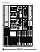
CODE
DESCRIPTION
= TEMP ACTUATED SWITCH
= RELAY or CONTACTOR COIL
= RELAY CONTACTS N. O.
= FIELD LINE VOLTAGE WIRING
= FIELD LOW VOLTAGE WIRING
= PRESSURE ACTUATED SW.
= RELAY CONTACTS N. C.
= PILOT LIGHT
= FACTORY WIRING
= THERMAL ELEMENT
= CIRCUIT BREAKER
= FUSE ELEMENT
= SWITCH
LEGEND
= TIME DELAY RELAY
= GRD = GROUND
FOR 230V, DISCONNECT RED LEAD AT H2, AND RECONNECT AT H3.
3. 208-230V UNITS: TRANSFORMER FACTORY WIRED FOR 208V OPERATION.
2. ALL WIRING TO THE UNIT MUST COMPLY WITH NEC AND LOCAL CODES.
1. COMPRESSOR MOTOR THERMALLY PROTECTED INTERNALLY.
NOTES:
R2
R1
Remote main fault relay
Compressor 1 start/stop switch
Compressor 2 start/stop switch
SW1
SW2
TRANS Transformer
Circuit 1 high pressure control switch (Manual reset)
Circuit 2 high pressure control switch (Manual reset)
Auxiliary Contacts 1 of Compr. 2 Contactor
Compressor 1
Compressor 2
Power on light
Main failure light
Low Voltage Terminal block (Main Control Panel)
Power Distribution Block
Compressor
1 fuse block
Compressor 2 fuse block
Compressor 1 Overload Module
Compressor 2 Overload Module
Control circuit fuse block #3, 1-pole, x-former sec.
Control circuit fuse block #4, 2-pole, x-former pri.
FB2
HPC1
HPC2
PDB
LVTB1
LT1
LT2
CCFB4
CC2AX1
CCFB3
COMP2
FB1
CPM1
CPM2
COMP1
DESCRIPTION
Compressor 1 contactor
Compressor 2 contactor
Auxiliary Contacts 1 of Compr. 1 Contactor
CODE
CC1AX1
CC1
CC2
This document is the sole property
of ClimaCool Corp. Distribution of
this document is forbidden without
the written consent of ClimaCool
Corp. Design changes to any
portion of this document may
occur without notice.
CB1
CB2
Compressor 2 circuit breaker (in lieu of compr fusing)
Compressor 1 circuit breaker (in lieu of compr fusing)
MVCH Motorized Valve, Chiller Outlet (Optional)
Control Relay, Motorized Valve, Evap. (Opt.)
R4
MVCHAX1
Auxiliary Contacts 1 of Chiller Motorized Valve (Opt.)
R5
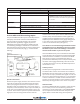
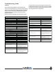
4. * COMPRESSOR FUSES SHOWN BELOW ON THE LEFT. CIRCUIT BREAKERS
SHOWN BELOW ON THE RIGHT ARE USED ON UCR(050/070)AH ONLY.
BE TYPE HACR CIRCUIT BREAKER OR EQUIVALENT, OR TYPE RK-5 FUSED
5. DISCONNECT SWITCH FOR UNIT TO BE PROVIDED BY OTHERS AND SHALL
DISCONNECT OR EQUIVALENT. (SEE DATA PL
ATE FOR SIZING.)
CCFB3
CB1, CB2
CCFB4
FB1, FB2
CCFB4
CCFB3
FB1, FB2
CCFB3
Fuse or C/B
CCFB4
UCR070AN...
UCR070AF...
UCR070AH...
Chiller Model #
Fuse or C/B
Amp Rating
Name
CCFB3
CB1, CB2
CCFB4
FB1, FB2
CCFB4
CCFB3
FB1, FB2
CCFB3
Fuse or C/B
CCFB4
UCR050AN...
UCR050AF...
UCR050AH...
Chiller Model #
Fuse or C/B
Amp Rating
Name
Control Cir.
Wire Ga.
60
75
6 ga.
4 ga.
Amp Rating
CC1, CC2
150
1/0 ga.
Wire Ga.
Compr.
50
60
8 ga.
6 ga.
Amp Rating
CC1, CC2
150
2 ga.
Compr.
Wire Ga.
180 lb-in
180 lb-in
375 lb-in
Torque
PDB Lugs
180 lb-in
180 lb-in
325 lb-in
Torque
PDB Lugs
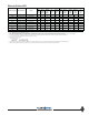
CCFB4
FB1, FB2
CCFB3
CCFB4
FB1, FB2
CCFB4
CCFB3
FB1, FB2
CCFB3
UCR030AF...
UCR030AN...
Chiller Model #
UCR030AH...
Control Cir.
Wire Ga.
CCH Watts
Trans. VA or
30
40
10 ga.
8 ga.
CC1, CC2
Amp Rating
75
4 ga.
Wire Ga.
Compr.
180 lb-in
180 lb-in
PDB Lugs
180 lb-in
Torque
MODEL FAMILY: UCR
Low Voltage Terminal block (Micro Cntrlr. & Sensor Panel)
LVTB2
Control Relay, Compressor #1
Control Relay, Compressor #2
Pressure Sensor (Transducer) #1, Compr. 1 Suct.
PS1
Pressure Sensor (Transducer) #2, Compr. 2 Suct.
PS2
Pressure Sensor (Transducer) #3, Compr. 1 Disch.
PS3
Pressure Sensor (Transducer) #4, Compr. 2 Disch.
PS4
Temp. Sensor #1, Compr. 1 Suct.
TS1
Temp. Sensor #2, Compr. 2 Suct.
TS2
Temp. Sens
or #3, Compr. 1 Disch.
TS3
TS4
Temp. Sensor #4, Compr. 2 Disch.
Temp. Sensor #5, Leaving Chilled Water
Temp. Sensor #6, Leaving Cond. Water
TS6
Comp. #1 on light
Comp. #2 on light
LT3
LT4
Elec. Diagram Module Power & Full Micro Controller
DATE 06/23/09
CEL-UCRxxxA(H/F/N)-2E.DWG
E
Modular Chiller Remote Air-Cooled Cond: UCR Product Family
Motorized Valves for Chilled Water Flow
LLS1
LLS2
Circuit 1 liquid line solenoid valve
Circuit 2 liquid line solemoid valve
DESCRIPTIONCODE
Compressor #1 Crankcase Heater
CCH1
Compressor #2 Crankcase Heater
CCH2
Control circuit fuse block #5, 2-pole, crankcase htr's
CCFB5
Auxiliary Contacts 2 of Compr. 2 Contactor
CC2AX2
Auxiliary Contacts 2 of Compr. 1 Contactor
CC1AX2
208-230
208-230
208-230
208-230
Fuse or C/B
Fuse or C/B
VAC
460
90
6
12
1.5
70
0.8
575
24
575
460
24
15
225
4.0
24
460
70
0.8
60
0.8
575
6
24
575
6
24
460
15
175
4.0
24
VAC
14 ga.
18 ga.
LPJ
LPJ
LP-CC
LP-CC
LP-CC
LP-CC
250
250
N/A
LP-CC
LP-CC
Fuse Type
500
Trans
VA Rating
14 ga.
18 ga.
18 ga.
LPJ
RK-5
LP-CC
LP-CC
LP-CC
LP-CC
250
150
N/A
LP-CC
LP-CC
Fuse Type
500
Trans
VA Rating
14 ga.
208-230
208-230
575
0.6
3.0
0.6
40
35
460
6
24
575
6
24
460
90
12
24
LP-CC
18 ga.
18 ga.
LP-CC
LP-CC
RK-5
LP-CC
RK-5
LP-CC
250 VA
150 VA
LPJ
LP-CC
250 VA
14 ga.
Fuse or C/B
Fuse or C/B
Amp Rating
Name
Fuse or C/B
VAC
Fuse Type
Control Cir.
Wire Ga.
TS5
CCFB5
CCFB5
CCFB5
208-230
575
0.5
1.25
0.6
460
LP-CC
LP-CC
LP-CC
90 W (x 2)
CCFB5
CCFB5
CCFB5
208-230
575
0.7
2.0
1.0
460
LP-CC
LP-CC
LP-CC
150 W (x 2)
150 W (x 2)
150 W (x 2)
CCFB5
CCFB5
CCFB5
208-230
575
0.7
2.0
1.0
460
LP-CC
LP-CC
LP-CC
150 W (x 2)
150 W (x 2)
150 W (x 2)
90 W (x 2)
90 W (x 2)