
Manual

15
www.climacoolcorp.com
Notes:
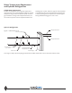
1. Figures 1 and 2 are required piping for proper water regulation and distribution through ClimaCool modular chillers.
2. Module order and incoming/outgoing water fl ow, as shown in both Figure 1 and 2, can be set up as either a left-to-right or right-to-left confi gura-
tion.
3. For chilled water (evaporator) inlet/outlet location dimensions, refer to page 10 - Dimension Data and Drawings.
4. A pressure diff erential fl ow switch is a required safety device for ClimaCool modular chillers on the chilled water circuit.
5. A strainer with a minimum of 60 mesh stainless steel screen is a required safety to protect the brazed plate heat exchanger on the chilled water
side of the system.
6. Maximum water fl ow rates for the evaporator water header system in one bank of modules is 1000 GPM.
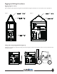
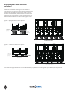
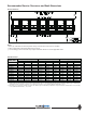
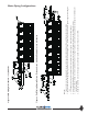
Figure 1- Field Piping Direct Return - 1 to 5 Modules
Figure 2 - Field Piping Reverse Return -(Preferred 1 to 5 modules) Required for 6 to 12 Modules
Water Piping Confi gurations