ENERGY RSH I P DE AN D L A LE • • TA L N O Installation, Operation & Maintenance Manual IRONMENTA TO Air Cooled Packaged Modular Chiller Model UCA V EN GR EEN SOL UT I
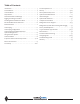
Table of Contents Introduction . . . . . . . . . . . . . . . . . . . . . . . . . . . . . . . . . . . . . . . . . 3 Pre-Startup Check List . . . . . . . . . . . . . . . . . . . . . . . . . . . . . . . . 22 Pre-Installation . . . . . . . . . . . . . . . . . . . . . . . . . . . . . . . . . . . . . . . 4 Startup . . . . . . . . . . . . . . . . . . . . . . . . . . . . . . . . . . . . . . . . . . 23-24 Unit Installation . . . . . . . . . . . . . . . . . . . . . . . . . . . . . . . . . . . . . .
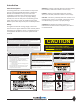
Introduction General Description ® Introducing ClimaCool’s newest addition to the product line: Air Cooled Packaged Modular Chiller - Model UCA. Modules are available in 20 and 30 tons and can be configured to provide project turndown and capacity requirements from 20 to 360 tons. By simply adding modules, the UCA can satisfy future incremental growth needs. This model is a quiet, serviceable and extremely efficient system that will provide years of reliable operation.
Pre-Installation Inspection Rigging and Lifting Upon receipt of equipment, carefully check the shipment against the bill of lading and inspect each chiller for any damage incurred during shipment. Thoroughly check for any visible damage of control panels, electrical and/or refrigeration components or broken copper lines.
Unit Installation Foundation for Unit Placement The minimum foundation requirement for the ClimaCool chiller is a level surface capable of bearing the combined operating weight of the modules (See Physical Data page 6). Service Access The recommended service clearances for front service access is 42”, unobstructed height clearance for airflow and 36” for rear service access as identified in the Recommended Service Clearances and Bank Dimensions on page 10 and 11.
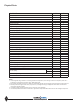
Physical Data Model UCA 20 30 Capacity (Tons)¹ 19.0 28.7 EER 10.8 10.8 2 2 Refrigerant Circuits (quantity) Compressor Type scroll scroll Compressor Quantity 2 2 Compressor Nominal Hp (per circuit) 10 15 Refrigerant Charge (per circuit) RͲ410A (lbs) 39 48 Module Operating Weight w/Water (lbs)³ 1,710 1,870 Module Shipping Weight (lbs)Ϻ 1,495 1,655 Condenser Fans 20 30 Motor Type T.E. T.E. HP 1.5 1.5 Quantity 1 2 Fan Type Axial Axial Diameter 31.5" 31.
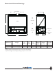
Dimensional Data and Drawings Air Discharge Air Discharge Air Intake Front B Chilled Water Intake Air Intake Chilled Water Outlet C A A B C Model UCA Voltage Unit Width Unit Height Unit Depth 020 030 208/230/460/575/3/60 208/230/460/575/3/60 83 3/4 83 3/4 84 84 39 3/4 39 3/4 Unit Weight1 (lbs) 1,495 1,655 Operating Header 2 Weight Connection (lbs) Size (in.) 1,710 6 1,870 6 Notes: 1. Shipping weight includes refrigerant charge, compressor oil and packaging. 2.
Rigging and Lifting Procedures Rigging Each module should be lifted by using lift straps threaded through the steel base cutouts and the use of a spreader bar. Lifting Strap Spreader Bar Spreader Bar Lifting Strap Spreader Bar Lifting and Transporting Modules Pallet jacks or forklifts are required for lifting and transporting the module. Each module has base cutouts provided for ease of maneuverability. 8 www.climacoolcorp.
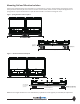
Mounting Rail and Vibration Isolation ClimaCool recommends locking down the chiller to a concrete base or to three 4” base mounting rails using the six bolt holes provided in each base pan. Due to the low vibration of the modules, ClimaCool does not require the application of spring isolators or pads. Should isolators or pads be desired install in accordance with Figures 1 and 2.
Recommended Service Clearances End-to-End Configuration Top View Rear Service Access See Note 4 for side clearance See Note 4 for side clearance Air Intake Air Intake Service and Air Intake Clearance Back-to-Back Configuration Service and Air Intake Clearance Air Intake See Note 4 for side clearance See Note 4 for side clearance Air Intake Service and Air Intake Clearance Notes: 1. Allow 42” clearance for electrical panels and 36” clearance for rear access to modules. 2.
Bank Dimensions Model UCA 1 Module 2 Modules 3 Modules 4 Modules 5 Modules 6 Modules 7 Modules 8 Modules 9 Modules 10 Modules 11 Modules 12 Modules Width (inches) Single (combine EndǦtoǦEnd with backǦtoǦback) ONLY 83 3/4 83 3/4 83 3/4 168 1/2 168 1/2 253 1/4 168 1/2 338 253 1/4 422 3/4 253 1/4 507 1/2 338 592 1/4 338 677 422 3/4 761 3/4 422 3/4 846 1/2 507 1/2 931 1/4 507 1/2 1016 Depth (inches) Single (combine with endǦtoǦend ) BackǦtoǦBack Ǧ 39 3/4 80 1/2 39 3/4 80 1/2 39 3/4 80 1/2 39 3/4 80 1/2 3
Water Piping As with any water system, it is important that the system be clean. The pipe work installer must remove weld scale, rust and contamination during pipe work fabrication. The system water piping must be flushed thoroughly with recommended alkaline flush or other chemicals that are compatible with 316 stainless steel prior to making connections to the ClimaCool chiller. There are certain necessary components that should always be installed in the chilled water system.
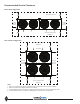
Water Piping Configurations Figure 1- Field Piping Direct Return - 1 to 5 Modules Figure 2 - Field Piping Reverse Return -(Preferred 1 to 5 modules) Required for more than 6 modules Notes: 1. Figures 1 and 2 are required piping for proper water regulation and distribution through ClimaCool modular chillers. 2. Module order and incoming/outgoing water flow, as shown in both Figure 1 and 2, can be set up as either a left-to-right or right-to-left configuration. 3.
Water Temperature Requirement and Hydronic Refrigeration Chilled Water Temperature Modudes are designed for a leaving water temperature range from 40°F to 62°F. All cataloged modules can operate safely in this range without the need of special controls or glycol additives. Leaving water temperatures below 40°F can result in evaporator suction temperatures below the freezing point of water.
Filling the Water System It is imperative that the water systems are free from debris prior to initial operation. See Water Treatment - page 16 for a comprehensive list of precautions. Cleaning the System Filling, Purging and Leak Testing the System 1. Whenever possible, install a temporary bypass line After the water system has been properly installed, a visual inspection should be made to all joints for tightness.
Water Treatment Water quality is of the utmost importance for the proper care and maintenance of the modular chiller system. Proper water treatment is a specialized industry and we recommend consulting an expert in this field to analyze the water for compliance with the water quality parameters listed in Table 1. The material used in the ClimaCool chiller exposed to the water are type 316 stainless steel, pure copper, and carbon steel. Other materials may exist external to the ClimaCool chiller.
Evaporator Water Pressure Drop Charts Evaporator Water Pressure Drop 20 & 30-Ton, 30 T "P k d Air-Cooled" Ai C l d" S i "Packaged Series 100 43.3 80 34.7 34 7 60 50 45 40 35 30 25 26.0 21.7 19.5 17.3 15.5 13 10.8 20 18 16 14 12 10 8.7 7.8 7.0 6.1 5.2 8 3.5 6 2.6 4 1.7 2 0.87 4.3 1 10 30 40 60 80 100 120 160 200 240 280 140 180 220 260 300 400 500 Pressure ure Drop (PSI) SI) Pressure ressure Drop (Ft. of Water) r) Model #: UCA020 & UCA030 0.43 1000 Flow (GPM) 17 www.
Evaporator Water Pressure Drop Charts Table 1 - Performance Adjustment Factors vs. Altitude vs. Chiller Temperature Drop Chiller Sea Level 2000 ft. 4000 ft. 6000 ft. Water Temp. Capacity Flow gpm kW Power Capacity Flow gpm kW Power Capacity Flow gpm kW Power Capacity Flow gpm kW Power °F Multiplier Multiplier Multiplier Multiplier Multiplier Multiplier Multiplier Multiplier Multiplier Multiplier Multiplier Multiplier 8 0.995 1.246 0.998 0.990 1.244 1.003 0.986 1.238 1.006 0.
Electrical Connection The compliance of the installation to relevant local and national codes is the responsibility of the installer. Before carrying out any electrical work, confirm that the main supply is isolated. The installer must ensure that the correct electrical drawing is available. Before power is applied to the system, the wiring should be visually inspected for loose connections or grayed terminal connections.
Pre-Startup All startups must be performed by ClimaCool factory trained personnel. Prior to chiller startup, there are certain essential checks which must be completed. Failure to carry out these checks could result in damage to the chiller voiding the modules warranty. Refrigeration 1. Refrigerant piping and components should be inspected for damage. 2.
Chiller Pre-Startup Procedures 1. Turn selector switches inside the module starter/control 2. 3. panel (low voltage side) to the off position. For future reference write the circuit number and power panel identification inside of the module control panel with a permanent marker. Ensure the correct fuses are installed in the control transformer fuse blocks inside of each ClimaCool module.
Pre StartͲUp Check List* (Packaged AirͲCooled) EͲmail customerservice@climacoolcorp.com or Fax to: 405Ͳ745Ͳ2072 Project Name: _________________________ Date: ___________________ Address: _________________________ _________________________ YES 1.
Startup All startups must be performed by ClimaCool factory trained personnel. 1. Built into the logic of the CoolLogic Control System 2. 3. 4. 5. 6. 7. is an anti-short cycle timer which will prevent the compressors from re-starting immediately following a compressor shutdown. If the chilled water temperature is above the normal operating level (greater than 90°F), all load should be removed from the chilled water system and the suction temperature should be monitored to prevent high current draw.
Caution: Do not charge to achieve subcooling temperature when the TXV is overfeeding. If the TXV is overfeeding, readings may still indicate low subcooling and low superheat, but circuit may not be undercharged.
StartͲUp and Warranty Registration Form (AirͲCooled) Sign, date and EͲmail to customerservice@climacoolcorp.com or Fax: (405) 745Ͳ2072 Attn: Customer Service.
StartͲUp and Warranty Registration Form (AirͲCooled) Sign, date and EͲmail to customerservice@climacoolcorp.com or Fax: (405) 745Ͳ2072 Attn: Customer Service.
Chiller Operation and Maintenance Pressure and Temperature Log Quarterly A log of temperatures and pressures should be taken regularly. Periodically conduct a visual inspection of the chiller to identify problems before they reach the point of failure. As with any mechanical system, it is necessary to conduct a series of checks to the ClimaCool chiller to confirm correct operation. Check controller operating parameters and setpoints. • Check temperature drop/rise on heat exchanger.
Heat Exchangers Draining When performing standard maintenance procedures such as flushing a heat exchanger, it will be necessary to close off a section of a module. This can easily be done if factory mounted water isolation valves are provided. Back Washing It may become evident from the recorded weekly log data that the performance of the chiller is gradually degrading. This could be due to a buildup of debris or sludge obstructing the free passage of flow through the heat exchangers.
Refrigerant Circuit #1 Refrigerant Circuit #2 Service Port (3/4”) Isolation Ball Valve (2”) Heat Exchanger Service Port (3/4”) Isolation Ball Valve (2”) Service Port (3/4”) Isolation Ball Valve (2”) Heat Exchanger Service Port (3/4”) Isolation Ball Valve (2”) Figure 1 - City Water Cleaning Arrangement Connected to City Water To Cooling Tower Header From Cooling Tower Header To Drain From Cooling Tower Header Header To Cooling Tower Connected to City Water Figure 2 - In Place Cleaning Arrange
Operational Limitations Voltage Limitations Compressor Operating Limitations UCA Maximum Compression Ratio 5.7:1 Minimum Operating Pressure Differential (psi) 85 Maximum Operating Pressure Differential (psi) 475 Minimum Discharge Pressure (psig) 235 The following voltage limitations are absolute and Maximum Discharge Pressure (psig) 590 operation beyond these limitations may cause Minimum Suction Pressure (No Glycol)(psig) 95 serious damage to the compressor.
Compressor Information Highly efficient and extremely reliable scroll compressors are used on Model UCA. The information contained in this manual will be useful for their care. Compressor Rotation All scroll-type machines are unidirectional and will only compress in one direction. Operating in the reverse rotation can be destructive and will be indicated by a loud operating noise together with a lack of compression.
Refrigeration Circuit Diagram FACTORY CHILLER WATER PIPING AIR COOLED CONDENSER SECTION CHILLER OUTLET WATER MAIN (6") CHILLER INLET WATER MAIN (6") 6 CHILLER WATER OUTLET VALVE (WHEN USED) CONDENSER AIR EXHAUST CONDENSER FAN(S) 7 CHILLER WATER INLET VALVE (WHEN USED) S2 FLUSH SHUT-OFF VALVE 8 S FILL SHUT-OFF VALVE PETE'S PORTS 5 9 REFRIGERANT CIRCUIT #1 REFRIGERANT CIRCUIT #2 TXV CONDENSER AIR INTAKE EQUALIZER LINE TXV BULB 10 COMPONENT LEGEND 4 3 EQUALIZER LINE S (WHEN USED) SYMBOL L
Refrigeration Circuit Diagram FACTORY CHILLER WATER PIPING 11 CHILLER OUTLET WATER MAIN (6") CHILLER INLET WATER MAIN (6") 10 9 AIR COOLED CONDENSER SECTION 8 12 CONDENSER AIR EXHAUST 7 CHILLER WATER OUTLET VALVE (WHEN USED) CONDENSER FAN(S) 13 CHILLER WATER INLET VALVE 6 (WHEN USED) S2 FLUSH SHUT-OFF VALVE R 14 FILL SHUT-OFF VALVE S C PETE'S PORTS D 5 15 LOCATE BULB SO IT SENSES OUTDOOR AIR REFRIGERANT CIRCUIT #1 REFRIGERANT CIRCUIT #2 TXV CONDENSER AIR INTAKE EQUALIZER LINE TXV
Refrigeration System Re-Processing and Charging Conforming to local and national codes is the responsibility of the service technician or installing contractor. The service technician should be familiar with the following codes: • ASHRAE Standard Safety Code for Mechanical Refrigeration, ANSI/ASHRAE 15-1978 • American National Standard Code for Pressure Piping, ANSI B31.5-1974 Factory Tested ClimaCool modular chillers have been pressure-tested, evacuated and charged with R-410A refrigerant.
Options Factory Installed Options Field Installed Options Low Ambient to -20oF Free Cooling Module Directly coupled to chiller bank, including free cooling coils, condenser fans and 3-way bypass valves. Pump Module Variable speed fan control for all condenser fans provides optimum head pressure control. Liquid receivers and flood-back head pressure control valves are provided for all refrigerant circuits.
“Y” Strainer Before installing the “Y” strainer, be sure its pressure rating is correct for the system. If the end connections are threaded or designed for soldering or brazing, be sure the piping is straight and not at an angle or offset. If the strainer has flanged ends, be sure the flanges of the connecting piping are square with the pipe so that no undue stress are put on the strainer or piping when tightening flange bolts. Tighten in sequence, crossing to opposites.
Basket Strainer Warning Cover Knobs Individuals performing removal and disassembly should be provided with suitable protection from possibly hazardous liquids. Knob and clamp type quick opening covers should not be used for high temperature service. Consult factory for recommendations. O-Ring Cover Installation O-Ring Before installing the simplex basket strainer, be sure its pressure rating is correct for the system.
Electrical Data ELECTRICAL DATA : Packaged Outdoor Air Cooled Chiller: UCA020 and UCA030 Base Chiller Models (MOP)3,8 Size Size 4,8 Fuse Rec. 60.0 150.0 Size 9 Switch Discon. 3.4 6.4 Amps1 Load Rated 4.3 8.0 (MCA)2 Amps Min.Cir. 6.0 7.5 12.0 (MOP)3 Size MaxFuse 14.1 17.6 38.9 Amps1 Load Rated 17.6 22.0 48.6 (MCA)2 Amps Min.Cir. 109.0 150.0 300.0 (LRA)5 Rotor Locked 35.0 40.0 90.0 (MOP)3 Size MaxFuse 35.0 40.0 70.0 Size 4 Fuse Rec.
Power Distribution Drawing Notes: 1. Breaker panel represents field power supply and is to be installed by others. Not provided as part of ClimaCool modular chiller system. 2. Breaker panels can be supplied for skid mount pump/tank packages or new construction projects as options. Consult your local ClimaCool representative. Control wiring is by others. 3. www.climacoolcorp.
Wiring Diagram - UCA020 40 www.climacoolcorp.
Wiring Diagram - UCA020 41 www.climacoolcorp.
Wiring Diagram - UCA030 42 www.climacoolcorp.
Wiring Diagram - UCA030 43 www.climacoolcorp.
Troubleshooting Guide WARNING! The troubleshooting guidelines recommended in this section could result in exposure to electrical safety hazards. Please refer to the safety warnings provided in this manual. Failure to follow all of the recommended safety warnings provided could result in death or serious injury. When possible, disconnect all electrical power including remote disconnects before servicing. Follow proper lockout-tagout procedures.
www.climacoolcorp.com forms\ccool\standard forms\word files\warranty certificate 05-10.doc Please refer to the CC Installation, Operation and Maintenance manual for operating and maintenance instructions. NOTE: Some states or Canadian provinces do not allow limitations on how long an implied warranty lasts, or the limitation or exclusion of consequential or incidental damages, so the foregoing exclusion and limitations may not apply to you.
L ENERGY RSH I P DE AN D IRONMENTA A LE V EN • • N TO I O TA L GR EEN SOL UT ISO 9001:2000 Certified Quality: First & Always 7300 S.W. 44th St. Oklahoma City, OK 73179 Phone: 405-745-3185 Fax: 405-745-2072 www.climacoolcorp.com ClimaCool works continually to improve its products. As a result, the design and speci cations of each product at the time for order may be changed without notice and may not be as described herein.