ClimaCool IOM FLEX SERIES Water-Cooled Modular Chillers Installation, Operation & Maintenance Manual ®
ClimaCool works continually to improve its products. As a result, the design and specifications of each product at the time for order may be changed without notice and may not be as described herein. Please contact ClimaCool's Customer Service Department at (405) 745-3185 for specific information on the current design and specifications.
ClimaCool Modular Chillers CONTENTS PAGES Model Numbers/Safety . . . . . . . . . . . . . . . . . . . . . . . . . . . . . 1 Inspection . . . . . . . . . . . . . . . . . . . . . . . . . . . . . . . . . . . . 2 Site Preparation . . . . . . . . . . . . . . . . . . . . . . . . . . . . . . . . . 3 Installation . . . . . . . . . . . . . . . . . . . . . . . . . . . . . . . . . . .
Inspection INSPECTION Handling of Modules The packaging allows for handling by fork lift or pallet jack (only lift the module from the side). See Lifting and Transporting Modules (Fig. 3) on page 5. Caution: modules ARE TOP HEAVY. Please use caution when rigging or moving. Allow a sufficient amount of time to carefully follow these instructions to assure warranty coverage. During inspection of the equipment remove the top doors to check the equipment for any damage during shipment.
Site Preparation/Installation Preparing for Installation. Prepare the modules for installation by carefully removing the module's packaging, unbolt the module from the skid, and lift the module with a crane or hoist into its final position. A factory supplied fastener kit is provided for the adjoining of each module. Each kit contains (4) gaskets, (32) ¾” fully threaded studs, (64) heavy duty hex nuts, (64) lock washers, and (64) flat washers.
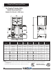
ClimaCool Dimensional Data ® The ClimaCool Modular Chiller Module Dimensional Data Models 30, 50 & 65 - FLEX Series Model FLEX Voltage Depth (inches) Width (inches) Height (inches) Height (w/covers) (inches) Weight1 (lbs.) Oper. Weight2 (lbs.
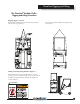
ClimaCool Rigging and Lifting ® The ClimaCool Modular Chiller Rigging and Lifting Procedures Rigging (Figures 1 and 2) Each module should be lifted by using lift straps threaded through each top header tube. A spreader bar should be utilized when rigging with covers in place. Lifting and Transporting Modules (Figure 3) When lifting and transporting the module, it is very important to proceed as shown at right.
ClimaCool Service Clearances ® The ClimaCool Modular Chiller Service Clearances Recommended Clearances 1. Allow 36” clearance for electrical panels and 24” clearance for rear service access to modules. 2. Allow a minimum of 18" height clearance for service and 12” for side clerances. 3. Local building or electrical codes may require additional clearance. Consult applicable codes. Modular Chiller Bank Dimensions - w/Connnection Flange Gaskets and Blank Off Plates Model Dimensions FLEX Width (ft.
ClimaCool Vibration Isolation ® The ClimaCool Modular Chiller Mounting Rail and Vibration Isolation Due to the low vibration of the modules, ClimaCool® does not require the application of spring isolators or pads. Should isolators or pads be desired, install in accordance with Figs. 1 and 2.
Electrical Connection Connecting the Water Piping to Modules Water piping must be installed in accordance with applicable codes and standards. Flexible connections and supports should be installed to prevent load or stress on the module's flange connections (see page 10 - Water Piping Configurations). Electrical Phase Sequencing Proper clockwise rotation for scroll compressor motors is important to prevent damaging the compressors.
Water Piping System WATER PIPING SYSTEM As with any water system, it is important that the system is clean. Care should be taken to maintain a clean system. The installing contractor should remove weld scale, rust and contamination during the fabrication of the piping system. We recommend the use of an alkaline flush of the piping system prior to start-up.
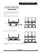
ClimaCool Water Piping Configurations ® The ClimaCool Modular Chiller - Field Piping Direct Return - 1 to 5 Modules (Figure 1) PressureTaps with Shutoff Valves & Gauges Thermometer Well Flow Switch Isolation Valve Unit 1 Unit 2 Unit 3 Unit 4 Unit 5 Blank Off Plates Flow Out Isolation Valves 60” Sensor Location (Field-Installed) Pump Flow In Strainer Thermometer Well PressureTap w/Shutoff Valve & Gauge Field Piping Reverse Return - (Preferred 1 to 5 modules) Required for 6 to 7 Modules (Figure
ClimaCool Hydronic Refrigeration ® The ClimaCool Modular Chiller - Figure 1 - Condenser Hydronic Circuit Isolation Ball Valve (2 or 2-1/2”) Pete’s Port Service Port (3/4”) Refrigerant Circuit #1 To Cooling Tower Header Refrigerant Circuit #2 From Cooling Tower Header Pete’s Port Isolation Ball Valve (2 or 2-1/2”) Service Port (3/4”) Heat Exchanger Figure 2 - Chilled Water Circuit Refrigerant Circuit #1 Isolation Ball Valve (2 or 2-1/2”) Pete’s Port Service Port (3/4”) Chilled Water Inlet H
Filling the Water System Pre-Start Up FILLING THE WATER SYSTEMS 4. After several hours of operation, the strainer should be isolated and cleaned. 5. Step 4 should be repeated until there is no more debris being collected by the strainer. 6. Finally, open all isolation valves inside each modular chiller and repeat step 4 and 5. It is imperative that the water systems are free from debris prior to initial operation. See the page 15 Water Treatment section for a comprehensive list of precautions.
ow Water Treatment ClimaCool Other ConsiderationsApplication Paramete ® WATER TREATMENT Proper water treatment is a specialized industry. We recommend consulting an expert in this field to analyze the water for compliance with the water quality parameters listed in Table 1 below. The material used in the ClimaCool chiller exposed to the water are type 316 stainless steel, pure copper, and carbon steel. Other materials may exist external to the ClimaCool chiller.
Condenser Water Temp. Requirements CONDENSER WATER TEMPERATURE REQUIREMENTS Requirements As a general rule the efficiency of the chiller increases as the condenser water temperature is lowered. The expansion valve, however, relies on the pressure difference across the valve to drive the liquid refrigerant through.
Stainless Steel Strainer Option CLIMACOOL CS STRAINER (OPTIONAL) damage to the strainer and screen in the event that water flow is stopped abruptly, or if water hammering occurs. The pressure relief valves should be set to relieve pressure at 1.2 times the strainer's maximum operating pressure (not to exceed the maximum rated pressure). Consult your local dealer or pressure relief valve manufacturer to obtain properly sized valves for your application. Fig.
Stainless Steel Strainer Option Table 1 STRAINER CS-2 (Clamp) CS-3 (Clamp) CS-4C (Clamp) CS-4B CS-6 CS-8 CS-10 BOLT SIZE 5/16 - 18 5/16 - 18 5/16 - 18 3/8 -16 1/2 - 13 1/2 - 13 5/8 - 11 RECOMMENDED TORQUE 40 - 50 in. lbs. 60 - 80 in. lbs. 75 - 85 in. lbs. 15 - 25 ft. lbs. 45 - 55 ft. lbs. 45 - 55 ft. lbs. 80 - 100 ft. lbs. BOLTED LID MODELS: ClimaCool Strainer models CS4B, CS-6, CS-8, and CS-10 have "bolted" lid designs.
Stainless Steel Strainer Option is preferable to use a hose with a significant amount of water pressure. DO NOT USE A PRESSURE WASHER Step 5: Wash all matter from the strainer gaskets and clean the inner-ring where the bottom of the strainer element rests. Step 6: Make sure the U-shaped gasket is fitted securely to the bottom of the strainer element. Reposition the strainer element into the body of the strainer. Step 7: Make sure the strainer head gasket is secure on the top of the strainer body.
Automatic Timer Flush Package Option reservoir. The power supply and timer controls for the valve package are housed inside the ATF control box. The ATF controls can be pre-programmed to set the flushing duration and the time interval between flushes. System Components: A. Timer Based Valve Controller (see Fig. 1) sets the flush duration (length of the flush) and the flush interval (time between flushes). B. Electric Ball Valve: designed for dirty water use (see Fig. 1 & 2).
Automatic Timer Flush Package Option when handling. Automatic Timer Flush ATF-EA-1.5 (optional) Valve Specifications A. B. C. D. E. F. G. Water-resistant Polypropylene Motor Case High Torque Motors with Perma-lube Gears Open & Close Indicator Stainless Steel Ball Valve & Hardware Auto Reset Circuit Breaker 90 Degree Bidirectional Rotation Controller Case Fig. 3 TROUBLESHOOTING: If you require further assistance, please call us at (405) 745-3185.
Automatic Timer Flush Package Option General Information Water Resistance: The Valve and Controller are water-resistant, but not waterproof. Do not install below ground level where the component can be submerged in water. Only remove the cover plate from the Valve Controller when setting or changing the flush settings. Keep the cover tightly sealed on the module during normal operation.
Pressure Differential Alarm Option Pressure Differential Alarm (PDA) option Visual Alarm Pressure Differential Switch-Gauge Differential Set-Point Contact TOP VIEW Visual Alarm LED Power Indicator Audible Alarm FRONT VIEW LEFT SIDE VIEW Power To ATF Cable Retainer Alarm Reset Button Cover-Plate Screw (4) in Corners of Box (DO NOT REMOVE).
Pressure Differential Alarm Option When the differential set point is reached, both the audible and visual alarms will be triggered and will remain engaged until both the Alarm condition is corrected, and the AlarmReset button is pressed. (If the Alarm-Reset button is pressed but the differential pressure is beyond the set point, the alarms will re-engage immediately).
Y Type & Basket Type Strainers ClimaCool Y Type & Basket Type Strainers Strainer Installation Instructions: A. Ensure all machined surfaces are free of defects and that the inside of the strainer is free of foreign objects. B. The strainer should be installed so that the drain connection is pointed downwards. C. For flanged end strainers, the flange bolting should be tightened gradually in a back and forth clockwise motion. Threaded end strainers should use an appropriate sealant. D.
Pre-Start Up 4. Place refrigerant gauges on the discharge and suction access ports of each refrigerant circuit to ensure a refrigerant charge is present. Leave the gauges on for compressor rotation check. 5. Confirm the settings on all pressure switches and thermostats. Pre-Start Up Prior to chiller start up, there are certain essential checks which must be carried out. Failure to carry out these checks could result in damage to the chiller voiding the warranty.
Start Up the "field wiring" terminal strip (terminals 8 &9). With jumper in place, turn on the selector switch marked "compressor #1" to bump the compressor and check for proper rotation. Use pressure gauges to verify proper rotation. Once this is complete and correct rotation is verified, override output with DX commissioning program or place a jumper between compressor 2 start terminals on the control terminal strip (terminals 10 & 11).
Pre Start Up Check List Pre Start-Up Check List* (Water-Cooled) ® T H E U LT I M AT E C H I L L E R S O L U T I O N ® E-mail vdoyle@climacoolcorp.
Start Up & Warranty Form ® T H E U LT I M AT E C H I L L E R S O L U T I O N ® Start-Up and Warranty Registration Form (Water-Cooled) Sign & date and fax: (405) 745-2072 Attn.: Vivian Doyle / Dennis Megaro Or E-mail: customerservice@climacoolcorp.
Chiller Operation and Maintenance CHILLER OPERATION AND MAINTENANCE Weekly • Review daily log from previous week • Perform visual inspection Pressure and Temperature Log A logRecommended of temperatures and pressures should be taken Maintenance Schedule• Properly document all data taken • Note any problems that may exist. Immediately plan for regularly. Periodically conduct a visual inspection further investigation.
Heat Exchangers higher than the normal flow, and, in the opposite direction. The difficulties and practicality of this method depends on the back wash pumping system itself. Another method would be to back flush each heat exchanger using city water as opposed to system water (see Fig. 1, City Water Cleaning Arrangement).
Operational Limitations VOLTAGE LIMITATIONS COMPRESSOR OPERATING LIMITATIONS The following voltage limitations are absolute and operation Maximum Compression Ratio ...................…. 7.0:1 beyond these limitations may cause serious damage Maximum Operating Pressure Differential (PSI) …… 240 Minimum Operating Pressuire Differential (PSI)…..…56 to the compressor. Maximum Suction Pressure (PSIG) ..............….. 80 o Maximum Discharge Temp. ( F) ....................
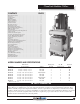
Physical Data ® The ClimaCool Modular Chiller Physical Data Models 30, 50 & 65 - FLEX Series Module and Compressors Model FLEX Capacity (Tons) Module Type Refrigerant Circuits (Quantity) Compressor Type Compressor Quantity Compressor Nominal Hp (Per Circuit) Minimum Unloading 2 (Tons / % Per Module) Refrigerant Charge (Per Circuit) R-22 (Lbs.) Oil Charge (Per Circuit) (Oz.) Module Overall Dimensions (Inches) 1 * Denotes unit with covers Module Operating Weight w/Water (Lbs.) 3 Module Shipping Weight (Lbs.
ClimaCool® Pressure Drops Application Parameters Condenser Water Pressure Drop 30, 50 & 65-Ton, "FLEX" Series Model #: MC2-50 Model #: MC2-65 43.3 80 34.7 60 50 45 40 35 30 25 26.0 21.7 19.5 17.3 15.5 13 20 18 16 14 12 10 8.7 7.8 7.0 6.1 5.2 8 3.5 6 2.6 4 1.7 2 0.87 10.8 4.3 1 10 30 40 60 80 100 120 140 160 200 240 280 350 400 180 220 260 300 Flow (GPM) Pressure Drop (PSI) Pressure Drop (Ft. of Water) Model #: MC2-25 & MC2-30 100 0.
Compressor Information COMPRESSOR INFORMATION The compressors used on the ClimaCool chiller are scroll compressors. They are highly efficient and extremely reliable. However, the information contained in this document will be useful for their care. Compressor Rotation All scroll-type machines are unidirectional and will only compress in one direction. Operating in the reverse rotation can be destructive and will be indicated by a load operating noise together with a lack of compression.
Refrigeration Circuit Diagram CHILLER WATER PIPING CHILLER OUTLET WATER MAIN (6") FLANGED CONDENSER WATER PIPING CONDENSER OUTLET WATER MAIN (6") FLANGED CHILLER INLET WATER MAIN (6") FLANGED CHILLER WATER OUTLET VALVE CONDENSER WATER OUTLET VALVE CHILLER WATER INLET VALVE 5 FLUSH SHUT-OFF VALVE S4 FILL SHUT-OFF VALVE CONDENSER INLET WATER MAIN (6") FLANGED 10 S3 FILL SHUT-OFF VALVE 6 7 8 9 CONDENSER WATER INLET VALVE FLUSH SHUT-OFF VALVE S2 PETE'S PORTS S1 PETE'S PORTS REFRIGERANT CI
Refrigeration Circuit Diagram CHILLER WATER PIPING CHILLER OUTLET WATER MAIN (6") FLANGED CONDENSER WATER PIPING CONDENSER OUTLET WATER MAIN (6") FLANGED CHILLER INLET WATER MAIN (6") FLANGED CHILLER WATER OUTLET VALVE CONDENSER WATER OUTLET VALVE CHILLER WATER INLET VALVE 5 FLUSH SHUT-OFF VALVE S4 FILL SHUT-OFF VALVE CONDENSER INLET WATER MAIN (6") FLANGED FILL SHUT-OFF VALVE 6 10 9 S3 7 8 CONDENSER WATER INLET VALVE FLUSH SHUT-OFF VALVE S2 PETE'S PORTS S1 PETE'S PORTS 14 REFRIGER
Refrigeration System Re-Processing REFRIGERATION SYSTEM RE-PROCESSING Conforming to local and national codes is the responsibility of the service technician or installing contractor. The service technician should be familiar with the following codes: ASHRAE Standard Safety Code for Mechanical Refrigeration, ANSI/ASHRAE 15-1978. American National Standard Code for Pressure Piping, ANSI B31.5-1974.
Sequence of Operation SEQUENCE OF OPERATION GENERIC INTERFACE - MANUAL ISOLATION VALVES modules of the chiller have one compressor running. The remaining compressors will stage per module, as load requires. Compressors shall be energized and de-energized by the program, in an order which will maintain equal run time. Sequence of Operations Chiller shall be enabled locally or remotely from enable/ disable contact by BAS via selector switch on face of the "Master Control Panel".
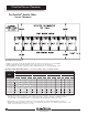
Electrical Data - 60 Hz ® The ClimaCool Modular Chiller Electrical® Data The ClimaCool Modular Chiller Models 30, 50 & 65 - FLEX Series Electrical Data Models 30, 50 & 65 - FLEX Series Model FLEX Voltage Power Wiring - per Module RLA1 Model 30 FLEX 30 Voltage 208-230/3/60 MCA2 MOP 3,8 Internal Wiring - per Compressor RLA1 Rec. Fuse 4,8 460/3/60 Power 92 103 Wiring 125- per Module 125 46 RLA1 MCA2 MOP 3,8 Rec.
Power Distribution ® The ClimaCool Modular Chiller Multi-Source Power Typical Installation Independent 115volt Power Supply Breaker Panel 1 115volt to Power Alarm For Optional Alarm Package CS Series Strainer Low Voltage (24v) Requires 60 Mesh Strainer or Optional 80 Mesh Strainer with Auto Flush and Alarm 6” condenser line (intake) ClimaCom™ Control Panel Mounting Rails - Required 4" Rail Minimum (by others) NOTES: 1. Breaker panel represents field power supply and is to be installed by others.
Module Power & Control Circuit ® T H E U LT I M AT E C H I L L E R S O L U T I O N ® ® 40 www.climacoolcorp.
Module Power & Control Circuit ® T H E U LT I M AT E C H I L L E R S O L U T I O N ® ® www.climacoolcorp.
Module Power & Control Circuit ® T H E U LT I M AT E C H I L L E R S O L U T I O N ® ® 42 www.climacoolcorp.
Troubleshooting Guide Troubleshooting Guide WARNING! The troubleshooting guidelines recommended in this section could result in exposure to electrical safety hazards. Refer to the safety warnings provided in this manual. Failure to follow all of the recommended safety warnings provided could result in death or serious injury. When possible, disconnect all electrical power including remote disconnects before servicing. Follow proper lockout-tagout procedures.
Troubleshooting Guide Troubleshooting Guide COMPRESSOR CYCLES ON HIGH PRESSURE CONTROL Possible Cause 1. Main condenser water valve closed 2. Water reg. valve incorrectly set or defective 3. Compressor discharge valve partially closed 4. Non-condensable gases in hydronic system 5. Overcharge of refrigerant (R-22 or R-407C) 6. Condenser water temperature high 7. Improper condenser water circulation 8. Insufficient water flow through the condenser 9. Fouled condenser brazed plate heat exchanger 10.
Warranty Certificate For complete warranty details refer to ClimaCool's web site at www.climacoolcorp.com or contact customer service at (405) 745-3185. CLIMACOOL CORPORATION LIMITED EXPRESS WARRANTY/LIMITATION OF REMEDIES AND LIABILITY WARRANTY DISCLAIMER It is expressly understood that unless a statement is specifically identified as a warranty, statements made by ClimaCool Corp.
® 7300 S.W. 44th St. Oklahoma City, OK 73179 405-745-3185 405-745-2072 (Fax) www.climacoolcorp.com ClimaCool is a subsidiary of LSB Industries Inc. NYSE symbol LXU; www.lsb-okc.com ClimaCool works continually to improve its products. As a result, the design and specifications of each product at the time for order may be changed without notice and may not be as described herein.