
Repair manual
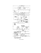


Step
TEST
RESULT
REMEDY
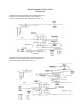
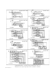
4. Are the following connections made correctly?
Yes Go to Step #5
A) COM input on board to boiler ground No
Correct probe wiring as required (see
Figure 1)
B) LO input on board to long length "LO" probe
C) HI input on board to short "HI" probe
5.
Temporarily disconnect the wire from the HTR
terminal so that the heat source will not
operate. Is the heat source off?
Yes
No
Go to Step #6
Check heat source and wiring in cooker
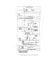
6. With HTR still disconnected, disc
onnect the
LOW wire at the LOW terminal of the con
trol
board. Measure the AC line voltage between the
HTR and L2 terminals on the con
trol board. Is
the voltage 0
vac? NOTE: Digital meters may
read a few volts due to their high input
impedance; this should be considered as 0 vac.
Yes
No
Go to Step #7
Replace water level control P/N 23198
7. Short the LOW and COM termi
nals on the control
board. Does the AC line voltage between the
HTR and L2 terminals now read 120
vac (line
voltage)?
Yes
No
Reconnect HTR &
LOW wires and go to
Step #8
Replace water level control P/N 23198
8. Disconnect the wires from the HI and COM
terminals on the control board and short the
HI &
COM terminals together. Measure the AC
line voltage between the WF and L2 termi
nals.
Is the voltage 0 vac?
Yes
No
Go to Step #9
Replace water level control P/N 23198