
Repair manual

HOW THE ELECTRIC (WARRICK
RELAY) WATER LEVEL CONTROLS
OPERATE — ON GAS FIRED STEAM
GENERATORS (WITH 3 PROBES)
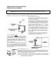
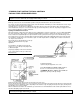
Inside Cleveland Range Co. boilers which have electric
water level controls, there are three probe extensions
vertically oriented above the water with their lower ends
positioned at various levels.
Water is admitted to the boiler and is shut off in response to
the water level sensed by the tips of the short and the
medium length probe extensions. The electncal conductance
of the water is used in this system for controlling its level.
The third probe extension is a low water safety cutout sensor
and operates on the same principle.
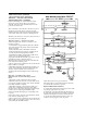
Operation Sequence — Water Level Control
Assume an empty boiler. To fill. dose Switch S for the
following operations:
1) Solenoid SV² is energized allowing the boiler to fill with
water at the same time the primary circuit of Transformer
T²is also energized.
2) The boiler will continue to fill until the water level
reaches the Water Off probe extension completing the T²
secondary circuit and energizing Relay Coil RC².
3) When Relay Coil RC² is energized the normally closed
contact opens, de-energizing Solenoid SV²
stopping the water fill. The normally open contact is closed,
completing the circuit to the Water On probe.
When the water boils away below the end of the Water On
probe extension the following occurs:
1) The secondary circuit of Transformer T² is broken and the
Relay Coil RC² is de energized.
2) When Relay Coil RC² is de-energized the normally open
contact opens, breaking the circuit to the Water Off probe
extension. And. the normally closed contact closes,
energizing Solenoid SV² allowing the boiler to fill as in Step
2 above.
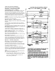
Operation — Low Water Safety Cutout
When Switch S is dosed the following operations
Occur:
1) The primary circuit of Transformer T² is energized.
2) When the water level reaches the low water safety cutout
probe extension and the momentary reset switch is manually
dosed. Relay Coil RC² is energized.
3) When Relay Coil RC², is energized the normally open
contacts close, completing the low water safety circuit
through Contacts 7 and 8 and completing the circuit through
Contacts 3 and 4. completing the 750 millivolt pilot
generator circuit and allowing the gas control package valve
to operate.
if the water level drops below the Low Water Safety Cutout
probe extension, the following occurs:
1) The secondary circuit of Transformer T² is broken and the
Relay Coil RC, is de-energized. Contacts 7 and 8 and 3 and 4
open. breaking the 750 millivolt circuit
which shuts oft the flow of gas to the burners-
The burners will not operate until water level in the boiler
is normal and the reset switch is operated.
Operation-Boiler Drain Condenser
To activate the Boiler Drain Condenser System dose switch
S by placing toggle in the down position.
To drain boiler, open boiler drain ball valve. The heat from
the boiler drain water will close the normally open thermal
switch TS and energize the condenser solenoid valve SV³
To de-activate the Boiler Drain Condenser System open
switch S by moving toggle to center off position.