
Repair manual

STANDING PILOT-IGNITION TYPE GAS CONTROLS
FOR GAS-FIRED STEAM GENERATORS
CAUTION: The following procedures, as well as other work on the gas controls, should be performed only by a trained and
experienced service technician, thoroughly familiar with gas controls.
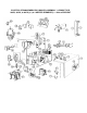
Built in gas controls assure sate and automatic operation of the pilot and main burners of the steam Generator
The controls consist of a pilot generator (thermocouple; and a unit called the combination gas control. This latter unit consists of a gas
valve operator and servo gas pressure regulator.
Generally, there is no need to make an adjustment to any portion of the gas system. The main burner orifices and the pilot burner
orifice installed at the factory are correct for the kind of gas specified on the purchase order. Also. the primary air supply to the main
burner is properly adjusted for complete combustion.
Lighting and Shutdown Instructions
Flip electrical switch on. Open water valve. Open gas valve. Slightly depress and turn control knob to "off" for 5 minutes before lighting
gas. Turn-control knob to "pilot," depress it completely and light pilot burner. Continue to hold knob in for about 60 seconds, then
release. Pilot burner is lighted through hole in panel at bottom of steam generator Never leave panel off, as this will damage controls.
Turn control knob to "on". Depress electrical switch for main burner ignition. Burners will not light without water in the steam generator.
For main burner off. with pilot on, turn control knob to "pilot". For main and pilot burner off, slightly depress and turn control knob to
"off". Flip electrical switch off.
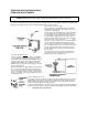
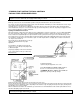
Occasionally, due to regional differences in the gas
supply, the pilot burner flame may require
adjustment.
A normal flame is mostly blue and steady, and
envelops 3/8" to 1/2 of the tip of the pilot generator,
as illustrated at right.
The pilot gas adjusting screw can be found under a
cover screw located near the gas control knob,
illustrated below.
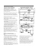
To adjust the pilot flame:
1) Remove the pilot adjustment cover screw.
2) Turn PILOT FLOW ADJUSTMENT SCREW clockwise to
decrease or counterclockwise increase pilot flame.
3) WARNING: Be sure to replace cover screw after
adjustment to prevent possible gas leakage.
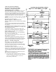
Electrical connections in the pilot generator circuit must be clean and secure.
Because the pilot generator operates in a severe environment, it may eventually need a replacement The time before replacement will
vary from one piece of equipment to another, depending on the amount of usage. The pilot generator (thermocouple) should generate
450-750 MV in an open circuit condition.
When a malfunction is traceable to the combination gas control unit. it is recommended that the entire unit be replaced with a new one,
rather than attempting repairs to the old unit.
WARNING: To prevent the danger of possible gas leakage, the installer must be a trained and experienced service
technician, thoroughly familiar with gas controls.