Cleveland Range REPAIR MANUAL PEM24/36/48-2/3J PEM160/200/250/300-2/3J PDL/PDM/PDP-2/3J Model NO. PSM-2/3J Cleveland Range, Inc. 1333 East 179th St. Cleveland, Ohio 44110 CANADA Garland Commercial Ranges • 1777 Kamato Rd.
Installation Instructions For Steam Generators, Steamers, Steamer/Kettles: Gas — Electric — Steam Coil Installation Instructions For All Models 1) These instructions must be retained by the owner/user for future reference. For installation only in noncombustible locations. Gas units are only to be installed in areas that have provisions for adequate air supply. 2) Position: For proper operation and drainage, steam generator must be level. It must be set near a floor drain.
7) Turn on electricity at control circuit switch on steamer console. A red light glows when electricity is on. If water level is correct, steam generator will operate by pressing the "reset" button. Heaters will not work without water in the steam generator This manual reset button must be pressed to start up the generator initially, and to restart the steam generator after every shut oft. or power interruption. No attempt should be made to operate the equipment during a power failure.
PRESSURE STEAMER OPERATING INSTRUCTIONS NOTE: These instructions pertain to steamers equipped with self-contained steam generators (boilers). For steamers directconnected to a remote (in-house) steam source, disregard those instructions which are directly and solely related to the selfcontained steam generator. These instructions are to be retained by the owner/user for future reference. 1A. Open the cabinet base door and close the drain valve if it is open.
7 Shelves, drain screens, and pan slides are stainless steel, and car be washed safely in a mechanical dishwasher. 8. Exterior Care: Allow steamer to cool before washing. Use the same cleaners and cleaning procedures as for other kitchen surfaces of stainless steel and aluminum. Mild soapy water, with a clear water rinse, is recommended. Do not allow water to run into electrical controls. Always turn off equipment power before using water to wash equipment.
PRESSURE STEAMERS: THERMOSTATIC TRAP AND COMPARTMENT DOOR GASKET REPLACEMENT The thermostatic trap and door gasket on your steamer stop the escape of steam from the compartment during operation Steam leakage from either source will cause loss of pressure which will result in longer cooking time, wasted steam and excessive condensation. T o keep your steamer operating at peak efficiency, thermostatic traps and compartment door gaskets require periodic replacement.
MECHANICAL COMPARTMENT CONTROLS MODEL J PRESSURE STEAMERS-JAN.
MECHANICAL COMPARTMENT CONTROLS MODEL J PRESSURE STEAMERS-JAN. 1982 THRU PRESENT REFERENCE NUMBER 1 2 3 4 6 PART NUMBER DESCRIPTION 8 9 10 11 12 4065O 22130 70411 22140 42276 42277 07173 42288 42289 02146 05263 20551 05252 22212 13 14 A B C 22213 41100 43765 40679 42697 D 40710 Pull Rod Handle Valve. Safely, 8 PSI Tee, Special 3/4" Air Vent Inlet Manifold Ass'y.—2-Compt.—Mech. "J", Less Valves Inlet Manifold Ass'y,—3-Compt,—Mech. "J", Less Valves Gauge. Pressure.
AUTOMATIC COMPARTMENT CONTROLS MODEL J PRESSURE STEAMERS-DEC.
AUTOMATIC COMPARTMENT CONTROLS MODEL J PRESSURE STEAMERS-DEC. 1977 THRU PRESENT REFERENCE NUMBER 1 2 3 4 5 13 14 15 16 17 18 19 20 21 22 A B C PART NUMBER 40860 22130 70411 22140 42296 42297 22115 03278 42288 42289 43764 05263 20551 22199 22185 07172 40518 19977 12161 07173 41350 40540 22212 22213 41100 43765 40879 40712 DESCRIPTION Pull Rod Handle Valve, Safely. 8 PSI Tee, Special 3/4" Air Vent Inlet Manifold Ass'y.—2-Compt.—Auto "J", Less Valves Intel Manifold Ass'y.—3-Compt.
MODEL J DOOR AND DOOR ARM ASSEMBLY REFERENCE NUMBER 1 2 3 4 5 6 7 8 9 10 11 12 13 14 15 16 17 18 19 20 21 PART NUMBER DESCRIPTION 253021 02568 41370 41371 081001 16305 15250 41360 43723 53035 04162 07136 68140 19228 23182 122001 163141 18306 023001 023061 14643 23181 Door Arm W/Bushings, Polished Door Ann Hinge Bushing (2 Required) Standard Door Arm Screw With Ball (1" x 8 thread) Oversize Door Arm Screw With Ball (1 3/32" x 8 thread) Screw Handle Bar, Polished Pin Oil Cup Striker Plate and Pin Door Ha
MODELS B, C, F, K PRESSURE STEAMERS DOOR AND DOOR ARM ASSEMBLY REFERENCE NUMBER 1 2 3 4 5 6 7 8 9 10 11 12 13 14 15 16 17 18 PART NUMBER DESCRIPTION 25303 25304 02568 41370 41371 081001 16305 15250 122011 122021 101018 163101 081031 19291 041631 04164 04165 07132 07134 023001 023061 14643 23181 40547 08601 08606 Door Ann With Bushings — Model B & C, Polished Door Arm With Bushings — Model F & K, Polished Door Ann Hinge Bushing (2 Required) Standard Door Ann Screw With Ball (1" x 8 thread) Oversize Door
MODELS J AND K PRESSURE STEAMER SLIDE SETS REFERENCE NUMBER 1 2 3 4 PART NUMBER 41440 41442 41430 41432 41435 41437 19909 DESCRIPTION Pan Support Slide Set, Model J Complete Pan Support Slide Set, Model K Complete Right or Left Side Slide Rack. 2 Per Compt Req'd. Model J Right or Left Side Slide Rack, 2 Per Compt Req'd, Model K Center Slide Rack Model J, 1 Req'd Per Compt Center Slide Rack Model K, 1 Req'd Per Compt Replacement Top Studs (Screw-In) J or K (Set of 6) CLEVELAND RANGE, INC.
START-UP MAINTENANCE PROCEDURES — STEAM GENERATOR IMPORTANT: These instructions must be followed in order to prevent premature failure of the steam generator. START-UP: 1) Open the cabinet base door and close the drain valve if it is open. (Red handle lever marked "blowdown".) 2) Rip the toggle switch on front of the cabinet console to "ON" (up position). The red console light should then glow and water will automatically begin filling the generator.
WATER QUALITY REQUIREMENTS — STEAM GENERATOR PROTECTION AND MAINTENANCE A steam generator, or broiler, unlike other types of water-using kitchen equipment, distills the water in order to make steam. Nearly all feed-water sources contain dissolved minerals in varying degrees of concentration. As this water is boiled, pure steam rises from it's surface, upward to the cooking compartment(s), leaving minerals behind that can become harmful to the steam generator.
MAINTENANCE INSTRUCTIONS FOR STEAM GENERATORS (EXCEPT THOSE EQUIPPED WITH TWO PROBES) WARNING: Steam under pressure may cause serious Injury and bodily harm when It is accidentally or carelessly released. Therefore, service of the steam generator should only be performed by trained and experienced personnel, thoroughly familiar with servicing steam generators. CAUTION: Never work on the steam generator when It is hot or pressurized.
STEAM GENERATOR (BOILER) IDENTIFICATION SERVICE NOTE The above drawings showing the sight gauge location and method of mounting are tor assisting in determining the proper part number tor replacement generators. When ordering, please provide both the proper part number and the equipment's serial number.
STEAM GENERATOR (2 PROBE TYPE) MAINTENANCE PROCEDURES CAUTION: Service on the generator must be performed only by a trained and experienced service technician, thoroughly familiar with servicing steam generators. No work should be done on the steam generator while it is pressurized or hot. Be sure all energy sources are shut off before the start of any work. The steam generator must be drained under pressure (blowdown) after a maximum of 8 hours of use.
WATER QUALITY REQUIREMENTS — 2-PROBE TYPE STEAM GENERATOR PROTECTION AND MAINTENANCE A steam generator, or boiler, unlike other types of water-using kitchen equipment, distills the water in order to make steam. Nearly all feed-water sources contain dissolved minerals in varying degrees of concentration. As this water is boiled, pure steam rises from its surface, upward to the cooking compartments), leaving minerals behind, that can become harmful to the steam generator.
Descaling Procedure for Two-Probe Steam Generators The steam generator should be descaled at least once a month, depending on scale buildup. If you have serious steam generator scale buildup, install a water treatment system for the steamer. Cleveland Range recommends use of the descaling kit, part number 40891, which consists of powdered sulfamic acid. Full descaling may take several hours, or more than one add process. Perform descaling until all scale buildup is cleaned out. (50-50).
Descaling Procedure (continued) 5. Turn off power at main disconnect switch. 26- Close the 3/4-inch manual drain valve. 6. Remove handhole plate. 27. Open 1/4-inch manual ball valve to fill assembly. 7. Pour powdered sulfamic add into the steam generator. 28- Turn electrical power on at main disconnect switch. 8. Replace handhole plate. 9. Turn water off at manual 1/4-inch ball valve on base. 10. Remove control box cover. 11. Disconnect black probe wire from water board. 12.
SERVICING INSTRUCTIONS STEAM PRESSURE ADJUSTMENTS WARNING: Adjustments must be made only by trained and experienced service personnel. Normally there is no need to make pressure adjustments on a new steamer, because the proper settings are made at the factory. In some cases however, the factory setting may shift due to shaking in transit, and resetting will be required after installation. The factory pressure settings shown on the accompanying chart should never be exceeded.
GAUGE PRESSURE READING WITH HO STEAM FLOW (STATIC PRESSURE) Self-Contained Steam Generator Self-Contained Direct-Connect Gas or Electric Steam Coil Generator (To "House" Steam Supply) Steamer's Pressure Reducing Valve Operating Pressure Switch High Limit Safety Pressure Switch Steamer's Pressure Reducing Valve Equipment Steam Generator Only Pressure Regulating Valve or Pressure Switch Steamer's Pressure Reducing Valve Kettle's Pressure Reducing Valve N/A 5 psi 10 psi N/A 5 psi N/A N/A P
SERVICING INSTRUCTIONS PROBE SYSTEM: ELECTRIC WATER FILL AND ELECTRIC LOW WATER FUEL CUT OFF FOR STEAM GENERATOR — 3 PROBE TYPE WARNING: Service of the steam generator must be performed only by trained and experienced service technicians.
SERVICING INSTRUCTIONS PROBE SYSTEM: ELECTRIC WATER FILL AND ELECTRIC LOW WATER FUEL CUT OFF FOR STEAM GENERATOR-- 3 PROBE TYPE 6) Assemble probe extensions to probes on inside of steam generator so they hang vertically, parallel to each otherMalfunctioning will occur if an extension touches any part of the steam generator or another probe extension 7) If insulation on electrical wires to the probe snows signs of being broken, cut or deteriorated, the wires should be replaced.
STANDING PILOT-IGNITION TYPE GAS CONTROLS FOR GAS-FIRED STEAM GENERATORS CAUTION: The following procedures, as well as other work on the gas controls, should be performed only by a trained and experienced service technician, thoroughly familiar with gas controls. Built in gas controls assure sate and automatic operation of the pilot and main burners of the steam Generator The controls consist of a pilot generator (thermocouple; and a unit called the combination gas control.
HOW THE ELECTRIC (WARRICK RELAY) WATER LEVEL CONTROLS OPERATE — ON GAS FIRED STEAM GENERATORS (WITH 3 PROBES) Inside Cleveland Range Co. boilers which have electric water level controls, there are three probe extensions vertically oriented above the water with their lower ends positioned at various levels. Water is admitted to the boiler and is shut off in response to the water level sensed by the tips of the short and the medium length probe extensions.
HOW THE ELECTRIC (WARRICK RELAY) WATER LEVEL CONTROLS OPERATE — ON ELECTRIC STEAM GENERATORS (WITH 3 PROBES) Inside Cleveland Range Co. boilers which have electric water level controls, there are three probe extensions vertically oriented above the water with their lower ends positioned at various levels. Water is admitted to the boiler and is shut off in response to the water level sensed by the tips of the short and the medium length probe extensions.
ELECTRIC STEAM GENERATOR (BOILER) ASSEMBLY - 3 PROBE TYPE 24KW, 36KW, & 48KW (2, 3, & 4 HEATER ELEMENTS) — 1968 to PRESENT
ELECTRIC STEAM GENERATOR (BOILER) ASSEMBLY 24KW, 36KW, & 48KW (2, 3, & 4 HEATER ELEMENTS) REFERENCE NUMBER 1 2 3 4 5 6 7 8 9 10 11 12 13 14 15 16 17 18 19 20 20A 21 22 23 24 25 26 27 28 29 30 31 32 33 34 35 36 37 - 3 PROBE TYPE 1968 to PRESENT PART DESCRIPTION NUMBER 43936 Boiler shell only. with legs, hand hole plate assembly, mounting studs tor 3 square-flanged heater elements.
ELECTRIC STEAM GENERATOR (BOILER) ASSEMBLY 18KW, 27KW, and 36KW (3 ELEMENTS — 6, 9, or 12KW EACH) — PRIOR TO 1968
REFERENCE NUMBER PART NUMBER DESCRIPTION 1 40425 Hand Hole Plate Assembly 16650 Hand Hole Plate Only 2 07116 Hand Hole Gasket 3 40446 Water Gauge Set With Glass 07108 Fiber Washer (2 Required) 23132 Gauge Glass Washer (2 Required) 4 07301 Glass Only — l0 1/2 Long 5 43720 Water Regulator Valve Assembly 6 06300 Float Only 7 43740 Float Arm and Block Assembly 8 02411 Float Pivot Bracket 9 23130 Sealing Washer 10 43735 Float Plunger Assem bly.
STEAM COIL GENERATOR (BOILER) ASSEMBLY 2 PROBE TYPE
STEAM COIL GENERATOR (BOILER) ASSEMBLY 2 PROBE TYPE REFERENCE NUMBER 1 2 2a 3 4 5 6 7 8 9 10 11 12 13 14 15 16 17 18 19 20 21 22 23 24 25 26 27 28 29 30 31 32 33 34 35 36 37 38 39 40 41 42 43 44 45 PART NUMBER DESCRIPTION 43977 Steam Coil Boiler Shell with Legs, Sight Gauge, Steam Coil, Hand Hole Plate Assembly, 2 Probes and Extensions with Cover Box.
ELECTRIC STEAM GENERATOR (BOILER) ASSEMBLY - 2 PROBE TYPE 18 KW, 27 KW, 36 KW, & 48 KW (2, 3, & 4 HEATER ELEMENTS) REFERENCE NUMBER PART NUMBER DESCRIPTION 1 43894 Electric Boiler Shell only. with legs. hand hole plate assembly, mounting studs tor 3' square flanged heater elements Electric Boiler Shell (43894) above, also include ing sight gauge, two probes and extensions with cow box. Hand Hole Plate Assembly including oar. nut. and gasket. Hand Hole Plate only Hand Hole Gasket.
HEATER AND CONTACTOR WIRING SCHEMATICS FOR SOLID STATE ELECTRIC STEAM GENERATORS
Electric Models
Electric Models with Secondary Low Water Cutoff Built to California Code
GAS STEAM GENERATOR (BOILER) ASSEMBLY - NO PROBES 100,000 BTU (2 BURNER) & 150,000 BTU (3 BURNER)
GAS STEAM GENERATOR (BOILER) ASSEMBLY — NO PROBES 100,000 BTU (2 BURNER) & 150,000 BTU (3 BURNER) REFERENCE NUMBER PART NUMBER DESCRIPTION 40300 40307 43826 Boiler Shell Only. With Legs, Studs. Hand Hole Plate Assembly, and Top Flue Bracket. Boiler Shell Only With Clip Locks. Studs. Hand Hole Plate Assembly, and Top Flue Bracket. Boiler Shell 40300 Above. Also Including One Corrosion Resistor, Sight Gauge. Low Water Cut-Off Switch, and Water Regulator Boiler Shell 40307 Above.
GAS STEAM GENERATOR (BOILER) ASSEMBLY — 3 PROBE TYPE 210,000 BTU (5 BURNERS)
GAS STEAM GENERATOR (BOILER) ASSEMBLY — 3 PROBE TYPE 210,000 BTU (5 BURNERS) REFERENCE NUMBER 1 PART NUMBER 40302 40309 43632 43833 2 2A 3 4 5 6 7 8 9 10 11 12 13 14 15 16 16A 17 40425 16545 07116 43895 40446 07108 23132 07301 40462 40455 52350 19870 44095 02499 02500 15453 15450 19632 19631 63152 22183 22189 43651 43653 18 19 20 21 21A 22 23 24 25 26 27 28 29 30 31 32 33 34 35 36 37 20410 02505 02523 15460 15461 52449 52450 52177 69933 07173 19941 19968 12161 19947 22140 22130 22131 22122 19945 03504
GAS STEAM GENERATOR (BOILER) ASSEMBLY — 3 PROBE TYPE 160,000 BTU (3 BURNER) & 200,000 BTU (4 BURNER)
GAS STEAM GENERATOR (BOILER) ASSEMBLY — 3 PROBE TYPE 160,000 BTU (3 BURNER) & 200,000 BTU (4 BURNER) REFERENCE NUMBER 1 2 2A 3 4 5 6 7 8 9 10 11 12 13 14 15 16 17 18 19 20 21 22 23 24 25 26 27 28 29 30 31 32 33 34 34A 35 36 37 38 39 40 41 42 43 44 45 46 47 48 49 PART DESCRIPTION NUMBER Boiler shell only.
GAS STEAM GENERATOR (BOILER) ASSEMBLY — 3 PROBE TYPE 250,000 BTU (5 BURNERS) & 300,000 BTU (6 BURNERS)
GAS STEAM GENERATOR (BOILER) ASSEMBLY — 3 PROBE TYPE 250,000 BTU (5 BURNERS) & 300,000 BTU (6 BURNERS) REFERENCE NUMBER 1 2 2A 3 4 5 6 7 8 9 10 11 12 13 14 15 16 17 18 19 20 21 22 23 24 25 26 27 28 29 30 31 32 33 33A 34 35 36 37 38 39 40 41 42 43 44 45 46 47 48 49 PART DESCRIPTION NUMBER 43873 Boiler shell only. with legs. Studs. tend hole plate assembly, and top flue bracket 40297 Boiler shell 43873 above, also including two corrosion resistors, sight gauge, insulation panels.
WIRING DIAGRAM FOR 100,000 and 150.
WIRING DIAGRAM FOR 100,000 and 150,000 BTU STEAM GENERATORS.
GAS STEAM GENERATOR (BOILER) ASSEMBLY - 2 PROBE TYPE SMALL: 100,000 BTU (2 Burners) & 200,000 BTU (4 burners) LARGE: 250,000 BTU (5 burners) & 300,000 BTU (6 burners)
GAS STEAM GENERATOR (BOILER) ASSEMBLY - 2 PROBE TYPE SMALL: 100,000 BTU (2 Burners) & 200,000 BTU (4 burners) LARGE: 250,000 BTU (5 burners) & 300,000 BTU (6 burners) REFERENCE NUMBER PART DESCRIPTION NUMBER 43898 44173 PART 44156 5-burner rear burner support BTU). with legs. studs. hand hole plate 44157 6-burner rear burner support 15 22130 Safety valve. 8 psi Large boiler shell only (250.000/300.000 BTU). with legs. studs, hand hole plate assembly, and top flue bracket 16 22131 Safety valve.
Gas Models
Gas Models with Secondary Low Water Cutoff
STEAM COIL GENERATOR (BOILER) ASSEMBLY WITH VARIOUS CONTROL OPTIONS (INCLUDES BOILERS EQUIPPED WITH 0, 1, or 3 PROBES)
STEAM COIL GENERATOR (BOILER) ASSEMBLY WITH VARIOUS CONTROL OPTIONS (INCLUDES BOILERS EQUIPPED WITH 0, 1, or 3 PROBES) REFERENCE NUMBER PART NUMBER DESCRIPTION 19 62453* 43700 Steam coil boiler shell with legs. sight gauge. water regulator, steam coil. one corrosion resistor, hand hole plate assembly. (For use with mechanical pressure regulating valve for controlling the steam supply.) Steam coil boiler shell (43700) above, also in cluding one probe and extension with cover box.
STEAM COIL WIRING DIAGRAM HOW THE ELECTRIC LOW WATER SAFETY SHUT -OFF OPERATES ON STEAM COIL (ELECTRIC OPERATED) STEAM GENERATORS Operation — Low Water Safety Shut-Off When Switch S is closed the following operations occur: 1. The primary circuit of Transformer T is energized. 2. When the water level reaches the low water safety cutout probe extension and the momentary reset switch is manually closed, Relay Coil RC is energized. 3.
SERVICING INSTRUCTIONS — MECHANICAL WATER FILL FOR STEAM GENERATOR The water level in the sight gauge should normally be about 2/3 full. If it is not. then (1) the water valve may be scaled up or (2) the water valve plunger disc is in need of replacement or (3) the adjusting screw at the top of the valve plunger is set incorrectly or (4) the float needs to be replaced. 10. Close steam generator drain valve. Turn on utilities and fuel. 11. Check the water level.
Steam Coil Models
Steam Coil Models with Secondary Low Water Cutoff
WATER LEVEL CONTROL SYSTEM TROUBLESHOOTING AND REPAIR General Description of Operation: The Cleveland Range water level control, P/N 23198, is designed to maintain operating water level in Cleveland Range steam generators and to ensure that the heat source is only operated when the generator water level is above a specified minimum level.
A) SYMPTOMS OF WATER LEVEL CONTROL RELATED PROBLEMS: 1) Boiler overfills or floods 2) Boiler dry fires (system underfills or doesn't fill) 3) Boiler doesn't fill at all 4) Water fill solenoid chatter 5) Heater contactor chatter 6) Fills but cuts out on LOW WATER before filling again 7) Overfills but does not heat 8) Fills but does not heat B) POSSIBLE CAUSES: 1) Inoperative water level control circuit board (P/N 23198) 2) Incorrect or damaged wiring to probes 3) Incorrect or damaged wiring from water leve
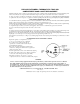
Step 4. TEST RESULT Are the following connections made correctly? Yes REMEDY Go to Step #5 A) COM input on board to boiler ground Correct probe wiring as required (see No Figure 1) B) LO input on board to long length "LO" probe C) HI input on board to short "HI" probe 5. Temporarily disconnect the wire from the HTR Yes Go to Step #6 terminal so that the heat source will not Check heat source and wiring in cooker No operate. Is the heat source off? 6.
STEP 9. 10. TEST RESULT Remove the short from the HI and COM terminals on the Yes REMEDY Reconnect El & COM wires and go to Step control board. Does the AC line voltage between WF #10 and L2 stay at 0 vac for about five seconds, then jump to No 120 vac? Replace water level control P/N 23198 Drain all water form the generator. Disconnect the wires Yes Go to Step #12 from the LO, HI, & COM terminals at the control board.
STEP 16. TEST RESULT Reconnect one lead of the ohmmeter to the COM wire at the Yes control board and connect the other ohmmeter lead to REMEDY Reconnect HI LOW & COM wires at control board only. Go to Step #17. generator ground. Does the ohmmeter read less than 10 ohms? 17. No Replace probe wiring Reconnect the ohmmeter across the LOW terminal at the Yes Go to Step #18 sensing probe & generator ground.
FIGURE 1 TWO-PROBE & COMMON WATER LEVEL CONTROL
WIRING DIAGRAM ELECTRIC STEAM GENERATORS WIRING DIAGRAM FOR ELECTRIC STEAM GENERATORS WITH ELECTRICAL LOW-WATER HEATER CUTOFF, WITHOUT MANUAL SAFETY RESET CIRCUIT PRIOR TO JANUARY, 1978 WIRING DIAGRAM FOR ELECTRIC STEAM GENERATORS WITH ELECTRICAL LOW-WATER HEATER CUTOFF.
CLEVELAND RANGE CO., 1333 EAST 179th ST., CLEVELAND, OHIO 44110 Manufacturer reserves right of design improvement or modification, as warranted. 0882 LITHO IN U.S.