
Operating instructions


INSPECTION
Before unpacking visually inspect the unit for evidence
of damage during shipping.
If damage is noticed, do not unpack the unit, follow
shipping damage instructions.
SHIPPING DAMAGE
INSTRUCTIONS
If shipping damage to the unit is discovered or
suspected, observe the following guidelines in
preparing a shipping damage claim.
1. Write down a description of the damage or the
reason for suspecting damage as soon as it is
discovered. This will help in filling out the claim
forms later.
2. As soon as damage is discovered or suspected,
notify the carrier that delivered the shipment.
3. Arrange for the carrier's representative to examine
the damage.
4. Fill out all carrier claims forms and have the
examining carrier sign and date each form.
GENERAL
Installation of the kettle must be accomplished by
qualified installation personnel working to all applicable
local and national codes. Improper installation of
product could cause injury or damage.
This equipment is built to comply with applicable
standards for manufacturers. Included among those
approval agencies are: UL, A.G.A., NSF, ASME/N.Bd.,
CSA, CGA, ETL, and others. Many local codes exist,
and it is the responsibility of the owner/installer to
comply with these codes.
Observe all clearance requirements to provide proper
make-up air flow. Do not obstruct the flow of combustion
and ventilation air. Check rating plate to ensure that
kettle has been equipped to operate with the type of
gas available at the installation.
Dimensions and clearance specifications are shown on
the specification sheet and in the Clearance
Requirements section.
CLEARANCE REQUIREMENTS
CLEARANCE REQUIREMENTS TO COMBUSTIBLE
AND NONCOMBUSTIBLE SURFACES.
NOTE: To prevent removal of unit for servicing, allow
sufficient room on right hand side for servicing.
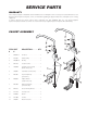
ASSEMBLY
Base Mounting Diagram
Table-top models must be positioned on a firm, level
stand (Cleveland ST-28 recommended), or existing
counter top, and bolted in place. These models are
supplied with four threaded mounting bushings welded to
the underside of the base. An optional support stand with
level adjustable legs is available. Once the kettle is
secure, screw tilt handle into the threaded hole provided
at the right side of kettle.
GAS
ENSURE THE GAS SUPPLY MATCHES THE
KETTLE'S REQUIREMENTS AS STATED ON THE
RATING PLATE.
It is recommended that a sediment trap (drip leg) be
installed in the gas supply line. If the gas pressure
exceeds 14” water column, a pressure regulator must
be installed, to provide a maximum of 14” water column
gas pressure to the gas control valve.
Connect the gas line to the manual valve located at the
rear of the control box.
14 1/2" 2
14 5/8"
10"
2 3/8" - 6 gallon
1 3/8" - 12 gallon
24" - 6 gallon
27" - 12 gallon
Model # Back Left Side Right Side
KGT-6-T 4” 0 0
KGT-12-T 4” 0 0
INSTALLATION