Operators Manual Installation, Operation & Service Gas Table Top Kettles MODELS: KGT-6-T KGT-12-T For models built after July 2002 ™ Cleveland Enodis 1333 East 179th St., Cleveland, Ohio, U.S.A. 44110 Phone: (216) 481-4900 Fax: (216) 481-3782 Visit our web site at www.clevelandrange.com SE95010 Rev.
FOR THE USER IMPORTANT! PRIOR TO REMOVING ANY FITTINGS ENSURE KETTLE IS AT ROOM TEMPERATURE AND PRESSURE GAUGE IS SHOWING ZERO OR LESS PRESSURE. FOR YOUR SAFETY DO NOT STORE OR USE GASOLINE OR ANY OTHER FLAMMABLE LIQUIDS AND VAPOURS IN THE VICINITY OF THIS OR ANY OTHER APPLIANCE. WARNING: Improper installation, adjustment, alteration, service or maintenance can cause property damage, injury or death.
INSTALLATION INSPECTION CLEARANCE REQUIREMENTS Before unpacking visually inspect the unit for evidence of damage during shipping. CLEARANCE REQUIREMENTS TO COMBUSTIBLE AND NONCOMBUSTIBLE SURFACES. If damage is noticed, do not unpack the unit, follow shipping damage instructions. SHIPPING DAMAGE INSTRUCTIONS If shipping damage to the unit is discovered or suspected, observe the following guidelines in preparing a shipping damage claim. 1.
Installation must be in accordance with local codes and/or the National Fuel Gas Code ANSI Z223.1 Latest Edition (USA) or the latest Installation Codes for Gas Burning Appliances and Equipment CAN/ CGA B149.1 and CAN/ CGA B149.2 (Canada). Use a gas pipe joint compound which is resistant to L.P. gas. Test all pipe joints for leaks with soap and water solution. Ensure that the gas pressure regulator is set for the manifold pressure indicated on the gas rating plate.
OPERATING INSTRUCTIONS 1 9 2 3 4 5 6 7 8 General Parts Drawing ITEM # DESCRIPTION FUNCTION 1. Tilting Handle Used for tilting the kettle. 2. Vacuum/Pressure Gauge Indicate steam pressure in PSI inside steam jacket as well as vacuum in inches of mercury. 3. Pressure Relief Valve This valve is used to vent the kettle and in the unlikely event there is an excess steam build-up in the jacket, this valve opens automatically to relieve this pressure. 4.
OPERATING THE KETTLE NOTE: Do not fill kettle above recommended level marked on outside of kettle. DO NOT ATTEMPT TO OPERATE THIS APPLIANCE DURING A POWER FAILURE. KEEP APPLIANCE AND AREA FREE AND CLEAR OF COMBUSTIBLES. DO NOT LEAN ON OR PLACE OBJECTS ON KETTLE LIP. SERIOUS INJURY COULD RESULT IF KETTLE TIPPED OVER, SPILLING HOT CONTENTS. 1. 2. Before turning kettle on, read the Vacuum/Pressure Gauge (2). The gauges needle should be in the green zone.
MARINE LOCK Your unit is equipped with a marine lock to prevent accidental tilting. The following procedure should be used to tilt the kettle. 2. 3. Hold the latch down to unlock tilting mechanism. Pull the handle to tilt kettle. 4. To lock, return the kettle to its upright position and push handle back. NOTE: Inspect lock daily to ensure it is free moving and does not bind or stick. Clean lock if necessary (see Cleaning Instructions below for details). 1. Grasp the tilt handle.
STAINLESS STEEL EQUIPMENT CARE AND CLEANING (Suppied courtesy of Nafem. For more information visit their web site at www.nafem.org) Contrary to popular belief, stainless steels ARE susceptible to rusting. 4. Treat your water. Though this is not always practical, softening hard water can do much to reduce deposits. There are certain filters that can be installed to remove distasteful and corrosive elements. To insure proper water treatment, call a treatment specialist. Corrosion on metals is everywhere.
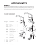
SERVICE PARTS WARRANTY Our Company supports a worldwide network of Maintenance and Repair Centers. Contact your nearest Maintenance and Repair Centre for replacement parts, service, or information regarding the proper maintenance and repair of your cooking equipment In order to preserve the various agency safety certification (UL, NSF, ASME/Ntl. Bd., etc.), only factory-supplied replacement parts should be used. The use of other than factory supplied replacement parts will void warranty.
CONSOLE COMPONENTS (used after June 2005) 14 15 7 1 3 2 4 10 12 11 13 19 6 5 9 8 16 20 21 17 18 ITEM # PART # DESCRIPTION 1. 2. 3. 4. 4. 5. 6. 7. 8. KE600545 KE50753-7 KE00458 KE50303-2 KE50303-1 FA11145 FA15018-7 FA11091 KE53838-20 KE53838-18 KE53838-27 KE53838-21 KE53469-2 KE600567 FA21006 FA15018-8 KE54309 KE54308-1 KE600566 FA11256 WHKGT-2 FA95074 FA31010 FA21026 COMPONENT MOUNTING BRACKET . . . . . . . . . . . . . . . . . . . . . . . . . . . . . . . . 1 RELAY . . . . . . . . . . . . .
CONSOLE COMPONENTS (used prior to June 2005) 7 9 11 10 2 4 12 5 8 6 3 1 16 14 15 13 ITEM # PART # DESCRIPTION 1-8 1. 2. 3. 4. 5. 6. 7. KE01928-3 KE01927-2 KE50753-7 KE00458 KE50303-2 FA11089 FA11052 KE53838-27 KE53838-21 KE53838-20 KE53838-18 KE53469-2 FA10245 KE54308-3 KE54309 WHKGT KE600252 KE90424 FA95062 COMPONENT PLATE ASSEMBLY . . . . . . . . . . . . . . . . . . . . . . . . . . . . . . . . . . . .1 COMPONENT MOUNTING PLATE WELDMENT . . . . . . . . . . . . . . . . . . . . . . . . .
TRUNNION ASSEMBLY (used after June 2005) 1 3 7 2 4 3 8 9 5 6 5 ITEM # PART # DESCRIPTION 1. 2. 3. 4. 5. 6. 7. 8. 9. FA21024 FA31030 KE600343 FA11323 KE01917-1 FA95007-11 FA05002-49 FA05002-45 KE54434-1 HEX NUT, SS, 5/16-18 . . . . . . . . . . . . . . . . . . . . . . . . . . . . . . . . . . . . . . . . . . . . 4 HELICAL SPRING LOCK WASHER, SS, 5/16" DIA. . . . . . . . . . . . . . . . . . . . . . . 4 BARTITE SEALING WASHER, 5/16" DIA. . . . . . . . . . . . . . . . . . . . . . . . . . . . . . .
SWITCHES & INDICATORS (used after June 2005) 5 6 4 1 2 3 6 5 7 8 4 9 3 7 8 10 2 1 60-B 05 KE60 OFF 9 ITEM # PART # DESCRIPTION QTY. 1. 2. 3. 4. 5. 6. 7. 8. 9. KE55486-3 KE55486-2 KE55486-4 KE600537 FA21006 KE600560-B SE00114 KE51005 KE50569-1 INDICATOR LIGHT, GREEN . . . . . . . . . . . . . . . . . . . . . . . . . . . . . . . . . . . . . . . . 1 INDICATOR LIGHT, RED . . . . . . . . . . . . . . . . . . . . . . . . . . . . . . . . . . . . . . . . . . 1 INDICATOR LIGHT, AMBER . . . . . . .
SWITCHES & INDICATORS (used prior to June 2005) 8 4 5 6 5 3 2 1 5 7 ITEM # PART # DESCRIPTION QTY. 1. 2. 3. 4. 5. 6. 7. 8. SE00114 KE51005 KE50569-1 KE50567-1 FA05002-18 KE50567-3 KE50567-2 KE5555-5 POTENTIOMETER WITH ON/OFF SWITCH, C/W ITEM #2 . . . . . . . . . . . . . . . . .1 ROTARY SEAL . . . . . . . . . . . . . . . . . . . . . . . . . . . . . . . . . . . . . . . . . . . . . . . . . . .1 KNOB, POTENTIOMETER . . . . . . . . . . . . . . . . . . . . . . . . . . . . . . . . . . . . . . . . . .
MAIN COMPONENTS 2 1 22 7 8 23 24 4 28 3 17 18 19 SEE FAUCET DRAWING 28 27 5 6 25 20 21 26 ITEM # PART # DESCRIPTION 1. 2. 3. 4. 5. 6. 7. 8. SK50403 SK50434 FA95081-3 KE54247 KE02004-2 KE50474 KE50429-5 KE54941-5 KE54941-31 KE50151-1 KE54670-4 KE54670-5 FA30501-1 KE54435-4 FA11258 KE54821-8 KE54721-2 KE54468 KE55069-6 KE50294-1 KE00515 KE54246-3 BRONZE BEARING . . . . . . . . . . . . . . . . . . . . . . . . . . . . . . . . . . . . . . . . . . . . . . .1 WASHER . . . . . . . . . . . . . . .
PIPING ASSEMBLY 5 17 6 16 7 13 15 4 3 11 8 9 10 TO MAIN GAS SUPPLY 14 1 2
PIPING ASSEMBLY (continued) ITEM # PART # DESCRIPTION 1. 2. KE01929-1 KE55240-8 KE55240-7 FI05163-1 FI05222-2 FEED PIPE ASS'Y . . . . . . . . . . . . . . . . . . . . . . . . . . . . . . . . . . . . . . . . . . . . . . . .1 GAS VALVE, NATURAL . . . . . . . . . . . . . . . . . . . . . . . . . . . . . . . . . . . . . . . . . . . .1 GAS VALVE, C/W L.P. CONVERSION KIT . . . . . . . . . . . . . . . . . . . . . . . . . . . . . .1 ADAPTER 1/2 NPT . . . . . . . . . . . . . . . . . . . . . . . . . . . . . . . .
MAINTENANCE ALL SERVICE MUST BE PERFORMED BY A QUALIFIED SERVICE TECHNICIAN. Cleveland Range equipment requires little preventative maintenance. We do however provide the following chart as a guideline for inspection and maintenance to keep your unit functioning at 100%. INSPECTION AND MAINTENANCE CHECK LIST The following check should be completed every six months or more frequently if unit is in a high volume facility.
CALIBRATING PROCEDURE 1. Insure the unit has a vacuum before you begin calibrating procedures. If unit requires venting refer to Kettle Venting Instructions. 2. Set On-Off Switch/Temperature Control to "10" (Max.). 3. Allow the unit to cycle twice. 4. Check temperature of the inner kettle surface with a digital surface thermometer. 5. Temperature should be between 260° F and 265° F. 6. Using a screw driver adjust temperature by turning the potentiometer on the black box. Turn very little.
RESERVOIR FILL PROCEDURES C. Fill unit via Street Elbow B. Attach Street Elbow WARNING: IMPROPER REFILLING OF KETTLE JACKET WILL RESULT IN IRREVERSIBLE DAMAGE TO UNIT. A.* Remove Pressure Relief Valve The kettle's water level must be maintained at the proper level. Under normal operating conditions, the sealed water reservoir should never require the addition of water.
KETTLE JACKET CLEANOUT AND PASSIVATION PROCEDURES The following procedure should be preformed at least once every three years to prevent possible corrosion and ensure the optimum life of the kettle. DANGER: WARNING: WORKING ON MACHINES WITH POWER COULD RESULT IN SEVERE ELECTRICAL SHOCK. IMPROPER REFILLING OF KETTLE JACKET WILL RESULT IN IRREVERSIBLE DAMAGE TO UNIT. DANGER: DANGER: MOLYFILM 315 IS CORROSIVE, AVOID CONTACT WITH SKIN AND EYES. EXTREMELY HOT SURFACES. WORK ONLY ON COLD KETTLE.
KETTLE VENTING INSTRUCTIONS 150 200 100 250 20 50 30 10 0 50 IR NT A VE Pressure Gauge Pressure Gauge Pressure Relief Valve Pressure Relief Valve 300 40 0 VACUUM LEAK TEST PROCEDURE 60 350 400 psi kPa Water Level Probe The following venting procedure should be followed when the Vacuum/Pressure Gauge needle is in the "VENT AIR" zone: NOTE: Check for and eliminate leaks prior to venting (See Repairing Leaks in Steam Jacketed Kettle Fittings.
WIRING DIAGRAM 4 1 2 6 4 7 9 5 8 10 8 12 3 14 13 11 15 ITEM # PART # DESCRIPTION 1. KE55486-2 KE50567-1 KE55486-3 KE50567-3 KE55486-2 KE50567-2 SE00114 KE00458 KE00515 KE50556-1 KE50753-7 KE50294-1 KE53838-27 KE53838-21 KE53437-1 KE55069-6 KE53469-2 KE53838-20 KE53838-18 KE55240-8 KE55240-7 L.E.D., RED (USED AFTER JUNE 2005) L.E.D., RED (USED PRIOR TO JUNE 2005) L.E.D., GREEN (USED AFTER JUNE 2005) L.E.D., GREEN (USED PRIOR TO JUNE 2005) L.E.D., AMBER (USED AFTER JUNE 2005) L.E.D.
OPERATING SEQUENCES 1. Turn On-Off Switch/ Temperature Control Knob "ON" * * * * 14 volt transformer is energized and powers solid state control system. Temperature knob is turned up and control box calls for heat. Relay (RY-1) closes and powers 24 volt transformer. Ignition control box is powered. 3. Ignitor Sparks * * Gas valve is energized. Ignitor sparks and ignition occurs. 4. Temperature Reached * * * * Solid state controls senses temperature reached.
MARINE LOCK TESTING PROCEDURE Marine Lock (Latch) Stop Pin on Sidebox Side to Side Play Lockwasher Locknut Figure A (Side View) 1. Check that lock clears stop pin on side box without rubbing when kettle is tilted (Figure A). Side Box 2. Check side to side play. Lock should remain fully over stop pin when pushed to it's maximum side to side play (Figure B). 3. Check that the kettle when pushed fully upright moves the lock to a closed position.