INTERMEDIATE TENSION CONTROLLER MWP – 12663 Instruction Manual AO-70174 (Rev BA)
Table Of Contents General Description ............................................................................................................. 4 Intermediate Drive System ...................................................................................................................4 Quickstart ............................................................................................................................. 5 Installation ..................................................................
Table Of Contents Additional Information ....................................................................................................... 19 External tension set point input...........................................................................................................19 Tension set point output .....................................................................................................................19 Adjusting the screen contrast ...............................................
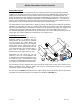
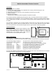
WebPro Intermediate Tension Controller General Description The WebPro Digital Tension Controller is part of a closed loop tension control system with transducer feedback. The Controller continuously controls the web tension to the TENSION SET POINT value and displays the true web tension on an LCD screen, either as a percentage or in engineering units. The screen will display the tension applied to each transducer separately by pressing the < LEFT tension or > RIGHT tension key.
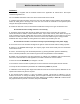
WebPro Intermediate Tension Controller Quickstart The Controller is supplied with the software loaded for the application as ordered but it will require commissioning before use. For more detailed information refer to the various sections later in this manual. 1. Carefully unpack the Controller, remove the rear cover and detach the bag containing the accessories. Attach the cable gland to the large hole in the rear cover. Mount the Controller in the operators panel using the two keyhole brackets provided.
WebPro Intermediate Tension Controller Installation The following parts are supplied:1. Controller, with software loaded for the application but requiring commissioning by the user. 2. Two keyhole mounting brackets. 3. Cable gland to be fitted to the rear cover and header connector kit for encoders. 4. Cabinet, if ordered. 5. Manual (this document).
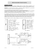
WebPro Intermediate Tension Controller Controller Connections WARNING - Disconnect the Controller completely before any electric welding is undertaken on the machine. Failure to carry out this precaution could damage the Controller and will invalidate the warranty. WARNING - The PCB uses devices sensitive to electrostatic voltages. Do NOT touch any components without first using proper electrostatic discharge ESD precautions.
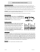
WebPro Intermediate Tension Controller Transducer Connections The Controller may be used with one half bridge transducer, two half bridge transducers, one full bridge transducer or two full bridge transducers. The strain gauges may be semiconductor with 5.6V or 10V DC excitation, each half bridge resistance 230S minimum; or foil with 10V DC excitation, each bridge resistance 350S minimum.
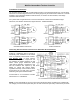
WebPro Intermediate Tension Controller Machine Sequence Logic and Connections, Digital Inputs WARNING - Do NOT connect the digital inputs to a negative or AC supply, this will cause damage and will invalidate the warranty. The digital inputs are opto-isolated and over voltage protected. The maximum input voltage is +24V DC. The AUTO/OFF functions may be selected from the keypad if Enable AUTO/OFF keys is Enabled. The full range of Machine Sequence Logic is selected externally, see Machine Parameters.
WebPro Intermediate Tension Controller Power Supply Connections The Controller may be powered by 110-120V, 220-240V 50/60Hz AC at 15VA or by 22-26V DC at 1A. Before connecting the Controller to the mains ensure that the mains voltage selector switch is set correctly. The mains supply is terminated on TB1, a two part connector. The mains fuse F1 is 160mA. The 24V DC supply must be smooth and free from noise. The 24V supply is terminated on TB4; positive to pin 1, negative to pin 2.
WebPro Intermediate Tension Controller System Set Up The system must be set up before the Controller is used for the first time. The on screen prompts are very easy to follow and will guide the user through the Controller system set up and commissioning. The parameters can be easily changed later if necessary. Press the SYSTEM SET UP key (called SET UP) to cancel an action or entry and return to the previous screen. Press the CONFIRM key when finished with a screen to confirm the entries.
WebPro Intermediate Tension Controller Machine Parameters From the Commissioning Menu; press 1 to show the Machine Parameters screen Machine Parameters (SET UP = cancel) Language English Deutsch Français Italiano Español Unit system S.I.
WebPro Intermediate Tension Controller Language (English, Deutsch, Français, Italiano, Español) The default language is English. If changed, all text shown on the Controller will be changed to that language and an extra item "5 - Translations" will be added to the Introduction screen. Unit system (SI (newtons), Kgf, pounds/foot, percent) Select a unit system. All items which use units will be changed accordingly.
WebPro Intermediate Tension Controller Output level bias (For Output trim only – NO) This item will output a signal at all times, for example to overcome friction in the controlled drive. The value of this item will reduce as the line speed increases so that at maximum line speed the bias is reduced to zero, this is because a maximum of 10V only can be output from the Controller. This bias does not operate with Output trim only - YES, the controlled drive should provide this.
WebPro Intermediate Tension Controller Follow the on screen prompts. Note The Tension must be calibrated before the Speed is calibrated. The Auto zero will compensate for the sensing roller weight and for any of the other analog zero offset voltages. Ensure that the line speed and reel speed signals and the external tension set point (if used) are at zero. The Controller will calibrate both transducers simultaneously.
WebPro Intermediate Tension Controller Possible error messages: Calibration has failed. Either the speed was much too low for accurate calibration, or the tachos and/or encoders are not operating correctly. Press the SET UP key to return to the Commissioning menu Calibration aborted. This is shown if the SET UP key is pressed. The Controller will return to the Commissioning Menu screen. Tension must be calibrated before speed. Select Calibrate tension from the menu.
WebPro Intermediate Tension Controller Controller Tuning It is essential that all motor drives are correctly set in accordance with the suppliers instructions BEFORE the Controller is commissioned. The Controller will not compensate for incorrectly set drives. PI Stability Settings There are two methods of setting the PI stability; through the Product Parameter menu with the machine at rest or through the Adjust PI stability menu with the machine running.
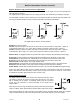
WebPro Intermediate Tension Controller Operating A typical Control screen is shown below. The Set Taper and Manual features do not operate with the Intermediate Controller. The Auto Tension set point may be set with the numeric keys followed by ENTER or by the +/- keys. The analog tension set point triangle is only visible when the Controller is in Auto control. The measured tension analog bar graph and the set point triangle should coincide when in control.
WebPro Intermediate Tension Controller Additional Information The CCFL ( cold cathode fluorescent light ) has a minimum expected life of 20,000 hours. The non-volatile memory is battery backed. The battery has an expected life of one year without a recharge. The battery will recharge when the Controller is powered. During power up the Controller may output a signal which may cause the machine to move if the controlled drive is powered and enabled.
WebPro Intermediate Tension Controller Installation Record Sheet Installation Date: Customer Address Machine name or type Purchase Order No. Controller Application System Units Output Range Tension Range Low High Minimum Tension Ramp Rate Damping Time Display Precision Friction Static Dynamic Tacho Yes / No Stop Time Product Number 1 2 3 4 5 6 7 8 9 10 11 12 13 14 15 16 17 18 19 20 Material Passwords Supply Voltage Stability Prop Integral Set Up ....................