
Owner manual

ULTRA SERIES UNDER PILLOW BLOCK TRANSDUCER MAN-70254 REV. AA
PAGE 16 OF 18
LEFT XDCR
8
7
6
3
4
5
2
1
1
2
3
BLK
WHT
BLU
BRN
6
5
4
8
7
WHT
BLU
BLK
BRN
1
1
2
3
4
2
3
4
RIGHT XDCR
CT
TC
CT
TC
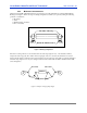
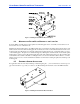
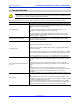
Figure 7 – Full Bridge Transducer Wiring
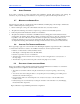
3.10 MATING CONNECTORS
The M12 connector used on the Ultra Series Under Pillow Block transducer is a four-pin, DC keyed, male connector
that mates directly with the molded corsets offered by Cleveland Motion Controls. The following table lists the pin
numbers and cable colors that apply:
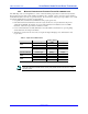
Pin Number Wire Color Signal
1 brown Excitation Voltage
2 white Output - (low going)
3 blue Excitation Return
4 black Output + (high going)
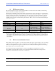
If you choose to make your own
cables or need to repair damaged
connectors, you can purchase a
separate mating connector from
Cleveland Motion Controls. To order,
use CMC part number, X44-34338.
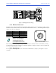
Figure 8 - Front View of M12 Connector
When mating the connector, align the keying mechanism and pins so that they enter the socket without you having
to apply excessive force. Use your fingers to sufficiently tighten the coupling nut enough to ensure an adequate seal
and to discourage accidental loosening.
3.11 CALIBRATION
For the proper calibration procedure, refer to the Instruction Manual that accompanied your amplifier or tension
controller.
2
1
3
4