
Owner manual

MAN-70254REV. AA ULTRA SERIES UNDER PILLOW BLOCK TRANSDUCER
PAGE 13 OF 18
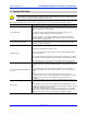
CORRECT
CORRECT
INCORRECT
INCORRECT
WEB FORCE
LOAD ZONE DIRECTION LABEL
3 INSTALLING THE UNDER PILLOW BLOCK TRANSDUCER
The following sections provide you with detailed information and steps to correctly install the Ultra Series Under
Pillow Block Transducer.
3.1 ORIENTING THE UNDER PILLOW BLOCK TRANSDUCER
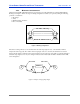
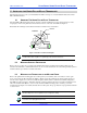
The Under Pillow Block transducer must be oriented so that the resultant tension force direction (bisector of the
wrap angle) is in the same quadrant as the load direction arrow on the side of the UPB. See Figure 4.
Ensure that the mounting location takes the transducer orientation into consideration.
Figure 4 –Transducer load direction Diagram.
The orientation is very important to ensure that the Transducer works as it was intended to. Incorrect
orientation will result in very little or no signal being produced from the transducer.
3.2 MOUNTING SURFACE PREPARATION
Remove any loose paint, rust or scale from the machine frame before mounting. The mounting surfaces for the
transducer should be flat to within 0.002 inches from one end of the transducer to the other. This generally requires a
machined surface upon which to mount the transducer.
3.3 MOUNTING THE TRANSDUCER TO THE MACHINE FRAME
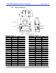
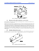
Remove the pillow block mounting plate (it is held in place by four stainless steel corner bolts) in order to gain
access to the four load cell mounting holes (Refer to Figure 5). For the mounting hole spacing pattern and proper
bolt size refer to Figure 3 in section 2.2.5. Drill and tap the machine frame to match the load cell mounting holes.
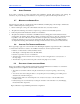
The UPB load cell is designed so that either imperial or metric mounting bolts can be used when mounting the load
cell to the machine frame (Refer to section 2.2.5). Orient the UPB load cell properly to obtain a good tension
measurement (See Figure 4 for details) and bolt the load cell in place. For proper fastener torque specifications Refer
to Section 2.2.4
The mounting surface must be flat to within 0.002 inches from one end of transducer to the other or the
transducer will produce an error signal due to the sensing beams flexing.
When tightening the mounting bolts use a criss-cross pattern and don’t fully tighten all the bolts until
each bolt has been lightly tightened down first.