INSTRUCTION MANUAL (MAN-70254) ® CLEVELAND-KIDDER ULTRA SERIES UNDER PILLOW BLOCK TRANSDUCER MODELS: UPB1 & UPB2 REVISION AA Industrial Products Division 7550 Hub Parkway Cleveland, Ohio 44125 Phone: 216.524.8800 Fax: 216.642.2131 www.CMCcontrols.
ULTRA SERIES UNDER PILLOW BLOCK TRANSDUCER REVISION HISTORY Rev ECO Author AA XXX RDL Date 01/31/2005 Description of Change As Released PAGE 2 OF 18 MAN-70254 REV.
MAN-70254REV. AA ULTRA SERIES UNDER PILLOW BLOCK TRANSDUCER TABLE OF CONTENTS 1 IMPORTANT INFORMATION .........................................................................5 1.1 ORDER NUMBERS ........................................................................................................... 5 1.2 CONTACT INFORMATION AND SERVICE ASSISTANCE .......................................................... 5 1.3 RECEIVING AND UNPACKING .....................................................................
ULTRA SERIES UNDER PILLOW BLOCK TRANSDUCER MAN-70254 REV. AA WARRANTY Cleveland Motion Controls warrants the goods against defects in design, materials and workmanship for the period of 12 months from the date of delivery on the terms detailed in the Cleveland Motion Controls, Inc. Terms and Conditions of Sale, document number AO-90131 Cleveland Motion Controls, Inc. reserves the right to change the content and product specification without notice.
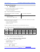
ULTRA SERIES UNDER PILLOW BLOCK TRANSDUCER MAN-70254REV. AA 1 IMPORTANT INFORMATION 1.1 ORDER NUMBERS Use the following example and Tables A to determine order numbers for: • Ultra Series Under Pillow Block Transducers • With or without mounting Plate Figure 1 – Example for Determining Transducer Order Numbers If you needed to Purchase a Transducer corresponding to following description: • Size 1 Under Pillow Block Transducer. • With Blank mounting plate. • Maximum Working Force (MWF) of 100 lbs.
ULTRA SERIES UNDER PILLOW BLOCK TRANSDUCER MAN-70254 REV. AA Disassembly by improperly trained personnel may result in additional damage to these units. Should repairs be required or for warranty repairs, contact the Customer Service Department for a return authorization number before returning the units. 1.
ULTRA SERIES UNDER PILLOW BLOCK TRANSDUCER MAN-70254REV. AA 1.4.3 CRITICAL ROLL SPEED Even with a balanced roll, a vibration can be set up in a stationary shaft. If this vibration (in cycles per minute) occurs at the harmonic frequency of the shaft, the transducers can be damaged. To determine critical roll speed, use the following formula: Critical roll speed in RPM = 4.8 x 10⁶ x Shaft O.D.
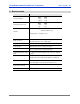
ULTRA SERIES UNDER PILLOW BLOCK TRANSDUCER MAN-70254 REV. AA 2 SPECIFICATIONS Item: Specification: Transducer Weight Mounting Plate with screws Material UPB1 UPB2 1.5 lbs. 0.68 kg. 12 lb. 5.4 kg UPB1 UPB2 2.2 lbs. 1 kg. 10 lb. 5 kg Strain Sensing beam – UPB1: 6061Aluminum UPB2: 410 Stainless steel Mounting Plate – 304 Stainless steel Finish Material UPB1 only: Anodized Aluminum Mounting Surface Flatness 0.002 inches from one side of transducer to the other.
ULTRA SERIES UNDER PILLOW BLOCK TRANSDUCER MAN-70254REV. AA 2.1 FORCE RATINGS Refer to Table A in this document for Transducer Maximum Working Force Ratings. 2.2 BEFORE INSTALLING THE TRANSDUCER Before installing the Transducer, perform the following steps: 1. Review the Installation Precautions (Section 2.2.1 on page 9). 2. Review the Safety Considerations (Section 2.2.2 on page 9) 3. Review the Mounting Configurations (Section 2.2.3 on page 10) 4.
ULTRA SERIES UNDER PILLOW BLOCK TRANSDUCER 2.2.3 MAN-70254 REV. AA MOUNTING CONFIGURATIONS Ultra Series Under Pillow Block Transducers are designed for use with shafts that are mounted in Pillow Block Bearings. See Figure 1.
ULTRA SERIES UNDER PILLOW BLOCK TRANSDUCER MAN-70254REV. AA 2.2.4 MOUNTING HARDWARE AND FASTENER TORQUE RECOMMENDATIONS The Table B provides you with guidelines to refer to when determining torque values for clean and dry fasteners. Keep in mind, however, that several variables can influence the “optimum” torque to be used in a given situation, and Table B should be used only as a general reference.
ULTRA SERIES UNDER PILLOW BLOCK TRANSDUCER 2.2.5 MAN-70254 REV. AA MOUNTING DIMENSIONS M N B A F G J PILLOW BLOCK E MOUNTING PLATE LOAD CELL K H D C W L Figure 3 – Mounting Dimensions Mounting dimensions in Inches: Designator: UPB1 A 1.5 B 0.55 C 5.8 D 1.5 E 5/16 (4) F 5.8 (Max.) G 1.6 H 1.95 I J 1/2 (Max.) (2) K 1.40 L 6.5 M 1.3 N 2.2 O P Q R S T U V W 2.2 X Y Z - Mounting dimensions in Millimeters: UPB2 3 0.80 10.0 3.0 1/2 (4) 10.0 (Max.) 3.0 2.5 3/4 (Max.) (4) 1.71 11.0 3.3 3.95 4.
ULTRA SERIES UNDER PILLOW BLOCK TRANSDUCER MAN-70254REV. AA 3 INSTALLING THE UNDER PILLOW BLOCK TRANSDUCER The following sections provide you with detailed information and steps to correctly install the Ultra Series Under Pillow Block Transducer. 3.1 ORIENTING THE UNDER PILLOW BLOCK TRANSDUCER The Under Pillow Block transducer must be oriented so that the resultant tension force direction (bisector of the wrap angle) is in the same quadrant as the load direction arrow on the side of the UPB.
ULTRA SERIES UNDER PILLOW BLOCK TRANSDUCER MAN-70254 REV. AA Figure 5 – Mounting the Under Pillow Block Transducer 3.4 MOUNTING THE PILLOW BLOCK BEARING TO THE LOAD CELL Note: The UPB is normally shipped with a pillow block mounting plate but is occasionally ordered without one if the customer chooses to make their own. Mounting the pillow block bearing to the UPB is simple and convenient. The mounting plate is held in place by four stainless steel corner bolts.
MAN-70254REV. AA 3.6 ULTRA SERIES UNDER PILLOW BLOCK TRANSDUCER SHAFT EXPANSION If the roller is subjected to higher temperatures after installation, thermal shaft expansion may damage the transducers. To prevent damage to the transducers, an expansion type pillow block bearing should be used. 3.7 MOUNTING THE SENSING ROLL The following steps take into consideration the risk and difficulty of handling large rolls and help to minimize the number of failed attempts at mounting the roll. 1.
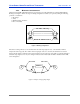
ULTRA SERIES UNDER PILLOW BLOCK TRANSDUCER MAN-70254 REV. AA RIGHT XDCR C T T C C T T C 1 1 2 3 4 5 6 7 8 1 2 3 4 5 6 7 8 BRN 4 BLK 2 WHT 3 BLU 1 BRN 4 BLK 2 WHT 3 BLU LEFT XDCR Figure 7 – Full Bridge Transducer Wiring 3.10 MATING CONNECTORS The M12 connector used on the Ultra Series Under Pillow Block transducer is a four-pin, DC keyed, male connector that mates directly with the molded corsets offered by Cleveland Motion Controls.
MAN-70254REV. AA ULTRA SERIES UNDER PILLOW BLOCK TRANSDUCER 4 TROUBLE SHOOTING Safety should not be an afterthought. Before installing, servicing or calibrating review and follow applicable policies and procedures to ensure worker safety. Machinery must be in a safe state and be aware of any additional hazards that can arise when installing and calibrating higher force transducers.
ULTRA SERIES UNDER PILLOW BLOCK TRANSDUCER 4.1 MAN-70254 REV. AA DC RESISTANCE CHECK If you have attempted to resolve your issue using the table above and have been unsuccessful, use the following checks to determine the viability of the transducer. The following nominal DC resistances table indicates a normal load cell, with no load applied at room temperature. The resistances are cited using both the wire color and the M12 connector pin numbers (Figure ).