
Manual

MAN-70434-0 REV AA ULTRA ISC SERIES SLIM CELL TRANSDUCER
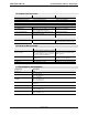
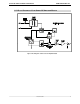
2.2 ELECTRICAL CONNECTIONS AND WIRING
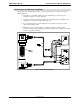
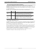
Refer to Figure 5 for making the transducer to power supply and tension controller connections.
Make certain that:
The cables do not interfere with the web path, and that they are away from power
transmission gearing or other moving parts.
You exercise care when routing the cables to avoid pick-up from noise-radiating power
cabling (motor armature leads, AC main wiring, etc).
In environments with severe electromagnetic noise, it may be necessary to route the
cables inside metallic conduit.
Polarity changes are accommodated by reversing the physical orientation of the
transducer, by interchanging the black and white output wires or by changing the settings
in the user’s application software.
Figure 5 Installation Wiring Diagram
PAGE 17 OF 42