Cleveland Motion Controls INSTRUCTION MANUAL (MAN-70434-0) FOR ULTRA ISC SERIES SLIM CELL TRANSDUCER REVISION AA
ULTRA ISC SERIES SLIM CELL TRANSDUCER MAN-70434-0 REV AA REVISION HISTORY Rev ECO Author AA XXX WGW Date Description of Change As Released This documentation may not be copied, photocopied, reproduced, translated, or reduced to any electronic medium or machine-readable format without explicit written permission from CLEVELAND MOTION CONTROLS. Copyright © 2007 by ITT, Cleveland Motion Controls Burny/AMC Division 7550 Hub Parkway Cleveland, Ohio 44125-5794 Tele: 216.524.8800 Fax: 216.642.
MAN-70434-0 REV AA ULTRA ISC SERIES SLIM CELL TRANSDUCER WARRANTY AND LIMITATION OF LIABILITY All equipment is sold subject to the mutual agreement that it is warranted by the company to be free from defects of material and workmanship but the company shall not be liable for special, indirect or consequential damages of any kind under this contract or otherwise.
ULTRA ISC SERIES SLIM CELL TRANSDUCER MAN-70434-0 REV AA BLANK PAGE 4 OF 42
MAN-70434-0 REV AA ULTRA ISC SERIES SLIM CELL TRANSDUCER TABLE OF CONTENTS 1 PRODUCT OVERVIEW ...................................................................................................... 9 1.1 GENERAL DESCRIPTION ...................................................................................................................... 9 1.2 FEATURES ........................................................................................................................................ 10 1.
ULTRA ISC SERIES SLIM CELL TRANSDUCER MAN-70434-0 REV AA 4.10 ADJUSTMENT TOOLS (ONLY IF NOT USING NUMERICAL CORRECTION).............................................. 34 4.11 GAIN AND ZERO CALIBRATION ........................................................................................................ 34 4.12 PROPER PRACTICES FOR APPLYING CALIBRATION FORCES .............................................................. 35 4.13 CALIBRATION ACCURACY CONSIDERATIONS .........................................
MAN-70434-0 REV AA ULTRA ISC SERIES SLIM CELL TRANSDUCER WARRANTY Cleveland Motion Controls warrants the goods against defects in design, materials and workmanship for the period of 12 months from the date of delivery on the terms detailed in the Cleveland Motion Controls, Inc. Terms and Conditions of Sale, document number AO-90131. Cleveland Motion Controls, Inc. reserves the right to change the content and product specification without notice.
ULTRA ISC SERIES SLIM CELL TRANSDUCER MAN-70434-0 REV AA BLANK PAGE 8 OF 42
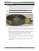
MAN-70434-0 REV AA ULTRA ISC SERIES SLIM CELL TRANSDUCER 1 PRODUCT OVERVIEW 1.1 GENERAL DESCRIPTION The Ultra Series Integrated Signal Conditioning (ISC) tension transducer (see Figure 1) outputs a +/- 10 VDC signal for reporting signals from strain gage-based load cells. Ultra ISC transducers include an Integrated Signal Conditioner (ISC) amplifier that is coupled directly to the “Ultra” type load cell employing semiconductor strain gages.
ULTRA ISC SERIES SLIM CELL TRANSDUCER MAN-70434-0 REV AA 1.2 FEATURES Ultra ISC tension transducer features are: Factory Calibration promotes interchangeability Tension controller observation of individual loadcell signals provides increased opportunity for advanced diagnostics and calibration.
MAN-70434-0 REV AA ULTRA ISC SERIES SLIM CELL TRANSDUCER 1.5 GENERAL SPECIFICATIONS Item Specification Comments 21.6-26.4 VDC @ 50mA Basic Isolated Amplifier 3.0 VDC FIXED Internally supplied. Calibration Range Min. 0.9 - Max. 9 Multi-turn Gain adjustment provided.
ULTRA ISC SERIES SLIM CELL TRANSDUCER MAN-70434-0 REV AA 1.8 OPERATING CONDITIONS Condition Isolated Signal Conditioning Amplifier Installation category Category III Pollution Pollution Degree 2 Input supply Earth (Ground) referenced Protection Enclosure mounted 1.
MAN-70434-0 REV AA ULTRA ISC SERIES SLIM CELL TRANSDUCER Output Impedance Approximately 64 Ohms per Bridge leg Maximum Voltage, Gage to Beam or Base (Ground) 50 Volts peak Operating Temperature Range 0 F to +200 F Maximum RPM 2500 (without derating) Alignment +/- 2 degrees angular displacement Break-away torque 0.6 lb-in o o 1.12 SLIM CELL FORCE RATINGS Size UltraSlim 1 UltraSlim 2 MWF (lb.
ULTRA ISC SERIES SLIM CELL TRANSDUCER MAN-70434-0 REV AA 1.
MAN-70434-0 REV AA ULTRA ISC SERIES SLIM CELL TRANSDUCER 2 PRODUCT COMPONENTS The Ultra Series ISC Slim Cell Tension Transducer (see Figure 3) consists of a housing that contains the amplifier and power supply boards that are coupled directly to an “Ultra” type load cell. There is an M12 connector to send amplified transducer signals into a tension controller, PLC, PAC, drive or local I/O. This housing has two access holes for gain and zero potentiometer adjustments if necessary.
ULTRA ISC SERIES SLIM CELL TRANSDUCER MAN-70434-0 REV AA 2.1 M12 MATING CONNECTOR The M12 connector used on the Ultra Series ISC amplifier is a four-pin, DC keyed, male connector that mates directly with the molded cordset offered by Cleveland Motion Controls. Table A lists the pin numbers, signal, function, wire colors and any notes that apply: When mating the connector, align the keying mechanism and pins so that they enter the socket without you having to apply excessive force.
MAN-70434-0 REV AA ULTRA ISC SERIES SLIM CELL TRANSDUCER 2.2 ELECTRICAL CONNECTIONS AND WIRING Refer to Figure 5 for making the transducer to power supply and tension controller connections. Make certain that: The cables do not interfere with the web path, and that they are away from power transmission gearing or other moving parts. You exercise care when routing the cables to avoid pick-up from noise-radiating power cabling (motor armature leads, AC main wiring, etc).
ULTRA ISC SERIES SLIM CELL TRANSDUCER MAN-70434-0 REV AA 2.3 CABLING Important: Most start-up problems are the result of mis-wiring or failure to reference the detailed information in this manual. Additional information details can be found in the subsequent sections of this manual and should be referenced before actual installation begins. The connector for the ISC is a standard 4-pin M12 quick-connect connector keyed for DC operation.
MAN-70434-0 REV AA ULTRA ISC SERIES SLIM CELL TRANSDUCER 2.4 POWER SUPPLY REQUIREMENTS For best performance, a regulated DC power supply that provides a nominal 24 VDC and at least 50 mA per ISC should be used. Important: Pay particular attention to the power supply for susceptibility to the effects of conducted and radiated energy from noise sources. Every effort should be made to provide stable voltage to the amplifier using correct wiring practices and filters.
ULTRA ISC SERIES SLIM CELL TRANSDUCER MAN-70434-0 REV AA 2.5 POTENTIOMETERS ADJUSTMENTS (IF NEEDED) The gain and zero adjustments are factory preset but accessible by the user for adjustment if absolutely necessary. Adjustment holes to access these potentiometers are visible on the side of the housing. Adjustments can be made by removing the sticker around the amplifier enclosure.
MAN-70434-0 REV AA ULTRA ISC SERIES SLIM CELL TRANSDUCER 3 PRODUCT APPLICATION The Ultra Series Slim Cell Transducer utilizes a twin sensing beam. Conversion from mechanical strain to an electrical signal is accomplished using semiconductor-based, piezoresistive strain gage elements. The Full Wheatstone Bridge configuration provides an electrically balanced output yielding twice the amount of signal swing as half-bridged transducers operated at the same excitation voltage.
ULTRA ISC SERIES SLIM CELL TRANSDUCER MAN-70434-0 REV AA 3.2 SUMMING In the majority of applications, loadcells are used in pairs. The net tension of the web must therefore be represented by the summation of the two loadcell signals. As described above, the summation can be done in software, so long as both analog channels can be independently observed. When only a single analog input is available, some other form of summer is required. Two simple approaches are described below.
MAN-70434-0 REV AA ULTRA ISC SERIES SLIM CELL TRANSDUCER 3.3 SUMMING BY “SERIES STACKING” The final interface approach to be discussed is to “stack” the two loadcell outputs by wiring the analog outputs to be “series aiding”. Note that with each loadcell outputs at a maximum of 5VDC, the sum would be 10 VDC. As should be obvious, loadcell signals greater than 5 VDC each will likely take most PLC analog inputs over-range.
ULTRA ISC SERIES SLIM CELL TRANSDUCER MAN-70434-0 REV AA 4 INSTALLATION 4.1 RECEIVING AND UNPACKING After receiving the Ultra ISC Slim Cell Transducer you should: Carefully unpack and handle the equipment Compare the received shipment with the packing list Report any damage to the carrier and your CMC representative Store equipment that will not be used in a clean, dry location Take appropriate precautions to prevent moisture, dust and dirt from accumulating in storage and installation areas 4.
MAN-70434-0 REV AA ULTRA ISC SERIES SLIM CELL TRANSDUCER 4.2.2 MOUNTING HARDWARE AND RECOMMENDED FASTENER TORQUE UltraSlim 1: ¼ - 20 x 1-3/8 “(typical) SAE grade 8 M6 - 1.0 x 35 mm L, Property Class 10.9 Setscrews 10 - 32 (Inch Hub) M5 - 0.8 (Metric Hub) Torque: UltraSlim 2: 3/8-16 x 2 (typical) SAE grade 8 M10 - 1.5 x 50 mm L, Property Class 10.9 Setscrews ¼ - 20 (Inch Hub) M6 - 1.0 (Metric Hub) Torque: 10 lb-ft 8 N-m 24 lb-in 4.7 N-m 32 lb-ft 45 N-m 7.
ULTRA ISC SERIES SLIM CELL TRANSDUCER MAN-70434-0 REV AA 4.2.3 MOUNTING DIMENSIONS G A S H B C Y T R N D E C W J Z M (BOLT DIA) X (BOLT DIA) U O BB P L V Q K AA1 OR AA2 I F 62 ° OF ANGULAR ALIGNMENT WITH BOLT IN POSITION MOUNTING BRACKET ( WITH SLIM CELL) SLIM CELL Mounting Dimensions for English Hardware: Dimension in Designator: Slim Cell Transducer 1: A 4.50 AA1 1.3 (mating conn. at right angle) AA2 2.5 (mating conn. straight) B 3.75 BB 1.08 C 2.996 3.000 D 1.50 E 0.625 0.
MAN-70434-0 REV AA Z ULTRA ISC SERIES SLIM CELL TRANSDUCER NC (3) 2.50 NC (3) 3.30 Z Table D Transducer and Mounting Bracket Dimensions PAGE 27 OF 42 NC (6) 63.5 NC (6) 83.
ULTRA ISC SERIES SLIM CELL TRANSDUCER MAN-70434-0 REV AA 4.2.4 SELECTING A MOUNTING LOCATION Select the mounting location for the transducer keeping the following points in mind: The transducer can be mounted to either inside or outside of the machine frame. The tension-sensing roll must not be mounted where the web wrap angle can vary, or the transducer will not interpret the tension properly as the angle varies.
MAN-70434-0 REV AA ULTRA ISC SERIES SLIM CELL TRANSDUCER 4.3 PRE-INSTALLATION PRECAUTIONS 4.3.1 SHIPPING Shock and vibration transmitted to the transducers by the sensing roll during transportation can damage the transducers. It is essential that you remove the sensing roll when the machine is shipped with the transducers mounted. 4.3.2 ROLL BALANCE The sensing roll must be adequately balanced.
ULTRA ISC SERIES SLIM CELL TRANSDUCER MAN-70434-0 REV AA 4.4 INSTALLATION PRECAUTIONS To ensure proper installation and operation of the system, keep the following points in mind: Do not apply shock loads to the Slim Cell bearing assembly when mounting or dismounting rolls. Exercise care to avoid overstressing the transducer when handling partially mounted rolls. Even relatively short rolls can afford an impressive mechanical advantage over the sensitive transducer.
MAN-70434-0 REV AA ULTRA ISC SERIES SLIM CELL TRANSDUCER 4.6 POSITIONING THE SLIM CELL TRANSDUCER Use the following steps when positioning the transducers for mounting: 1. Before bolting the transducer in place, be sure that it is generally aligned with the tension force (load direction).
ULTRA ISC SERIES SLIM CELL TRANSDUCER MAN-70434-0 REV AA 4.7 MOUNTING THE SENSING ROLL Be sure to exercise care during this portion of the installation, as it easy to produce excessive force on the transducer sensing beams. To mount the roll, use the following steps: 1. Loosely fit the roll into the transducer to verify that the shaft and the adapter fit without excessive interference or clearance. For reference, the bore diameter of the hub is +0.0007 and +0.0017 in. (+0.018 and +0.
MAN-70434-0 REV AA ULTRA ISC SERIES SLIM CELL TRANSDUCER 4.9 POWER-UP AND TESTING 4.9.1 BEFORE APPLYING POWER Before applying power, check the wiring to the amplifier. Pay particular attention to the following: Double check the transducer cabling to ensure that the 24V power supply is within limits and polarity is correct. Use an approved anti-static wrist strap when adjusting any potentiometers on the amplifier.
ULTRA ISC SERIES SLIM CELL TRANSDUCER MAN-70434-0 REV AA 4.10 ADJUSTMENT TOOLS (ONLY IF NOT USING NUMERICAL CORRECTION) Using the correct tools simplifies the setup process and necessary adjustments. Keep the following points in mind: The Integrated Signal Conditioning Amplifier utilizes two different potentiometers. The Gain and Zero adjustments are located on the side of the amplifier (under the sticker). The adjustment tool should have dimension on the order of 0.5mm (.
MAN-70434-0 REV AA ULTRA ISC SERIES SLIM CELL TRANSDUCER 4.12 PROPER PRACTICES FOR APPLYING CALIBRATION FORCES Seldom is a transducer oriented such that the calibration can be done by simply hanging a true dead weight from the roll. By generating a tension force that follows the same web path across the roll, you avoid the necessity of making manual (numerical) calculations to correct for the details of different wrap angle, transducer orientation, etc.
ULTRA ISC SERIES SLIM CELL TRANSDUCER MAN-70434-0 REV AA Examples of Force Loss due to Friction at Driven Roll In this example, only a fraction of the test force is transferred to the transducer due to drag from the driven roll. In this example, by rearranging the anchor point and the force location as well as utilizing the idle roll, the frictional losses are minimized. 4.
MAN-70434-0 REV AA ULTRA ISC SERIES SLIM CELL TRANSDUCER Always apply and remove the test load in a continuously increasing or decreasing manner, so that the force changes are monotonic. This helps to avoid disturbing any hysteresis component of the transducers force signal. When calibrating for a particularly wide roll that will always have a narrower product tracking to one side, consider applying the calibration force at the roll position that represents the center of the product.
ULTRA ISC SERIES SLIM CELL TRANSDUCER MAN-70434-0 REV AA 4.15 EMC CONNECTIONS AND INSTALLATION Compliance with the specified EMC directive for immunity in a heavy industrial environment and emissions in a light industrial environment requires correct installation and wiring of the Ultra ISC Tension Transducer.
MAN-70434-0 REV AA ULTRA ISC SERIES SLIM CELL TRANSDUCER 4.16 CABLE GLANDS Several manufacturers provide cable glands that can be used to ensure the integrity of the EMC requirements when installing this equipment in the enclosure. The objective of the cable gland is to provide a good mechanical entry into the enclosure to protect the cable and also provide an electrical bond the outer shield (screen) of the cable to the enclosure.
ULTRA ISC SERIES SLIM CELL TRANSDUCER MAN-70434-0 REV AA 5 TROUBLESHOOTING Do no let safety be an afterthought! Before installing, servicing or calibrating review and follow applicable policies and procedures to ensure worker safety. Machinery must be in a safe state and be aware of any additional hazards that can arise when installing and calibrating higher force transducers.
MAN-70434-0 REV AA ULTRA ISC SERIES SLIM CELL TRANSDUCER 5.1 TRANSDUCER BENCH TESTING Because the strain gage signal conditioning is completely internal to the transducer, it is impractical to directly measure the resistance of the stain gage elements. This complicates the task of bench testing. However, there are measurable indications of the potential functionality. 1. Measure the DC load current powering the ISC. An in-line Digital Multi-meter (DMM) set up to measure DC milliamps can be used.
ULTRA ISC SERIES SLIM CELL TRANSDUCER MAN-70434-0 REV AA 6 MANUFACTURERS DECLARATION OF CONFORMITY Figure 13 EC Declaration of Conformity PAGE 42 OF 42